Key Terms
commutator
electromagnet
Hall sensor
motors
relay
rotor (armature)
solenoid
stator

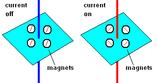
Orsted discovered a connection between electricity and magnetism (animation)
When a current flows through a wire, a magnetic field is produced around the wire. This was first demonstrated in 1820 by Hans Christian Orsted. As long as the current flow is steady DC current ... the magnetic field will remain uniform. This magnetic field becomes magnified when a current carrying wire is wrapped around an iron bar. The more windings around the iron bar, the stronger the surrounding magnetic field. The metal bar helps to concentrate the magnetic field. Try this simple demonstration: Wrap an insulated copper wire around an iron nail several times and attach each end of the wire to the terminals of a flashlight battery. As long as current flows through the wire, the nail will then be able to pick small metal objects like paper clips.
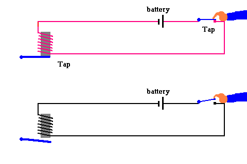
The telegraph (animation)
The telegraph revolutionized communications. At its heart was an electromagnet where the entire circuit of wires stretched several miles between towns. Electromagnets are currently used in assembly lines, junk yards and recycle centers to pick up heavy iron objects.
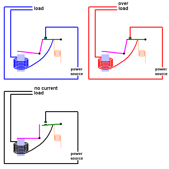
The electromagnetic circuit breaker (animation)
Modern circuit breakers use an electromagnet to open a circuit when too much current goes through a line. An ordinary fuse (link 3.3.a) will simply overheat a thin wire ... the fuse will blow (melt the wire) and breaks the circuit. This means you have to replace the fuse with a new one, but circuit breakers can be reset by flipping a switch.
Analog Meters
Analog meters have been around for quite some time. They can measure anything from volts, amps (electric current), electrical resistance, temperature, pressure, .... just about anything that you can measure and convert to an electric current. Inside the meter you will find a movable spindle with a coil of wires wrapped around it. Surrounding this spindle is a permanent magnet. When current flows in the wire, it becomes an electromagnet and interacts with the surrounding magnetic field. This causes the spindle to rotate as magnetic forces interact. The greater the current in the wires, the stronger the magnetic field, ... which provides a higher dial reading.
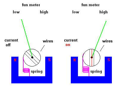
Meter animation (are we having fun?)
The interaction between permanent magnets and electromagnets is explored in more detail below when we discuss electric motors.
(animation)
A solenoid consists of a coil of wires with a metal plunger that is able to move freely within the coil. When the current is applied and the magnetic field builds, a metal plunger is drawn into the housing. When the current is removed and the magnetic field collapses, the plunger is then pulled out of the housing by a spring.
Everyone has a doorbell but have you ever looked inside to see what makes the ding-dong? You guessed it ... a solenoid. The animation (below) shows that a metal section of a rod is drawn into the solenoid when the coils are energized. This causes the rod to strike a xylophone ... DING! There is a retracting spring which makes the rod hit another xylophone on the rebound ... DONG!
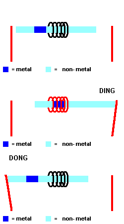
The common doorbell (animation)
A solenoid is used every time you start your car. A solenoid engages the starter motor's bendix gear with the flywheel. This turns the engine over and, hopefully, the gasoline engine runs on its own. At that point the solenoid is deactivated and a spring retracts the bendix gear from the flywheel. Solenoids also open your locks when you press the unlock button on your car (at least in older cars ... modern cars may use tiny electric motors). There are solenoids in anti-lock braking systems ... one to isolate the brake fluid of a skidding wheel from the rest of the fluid system ... and another is used to "pump" the brakes at superhuman speeds. When you put your SUV into 4 wheel drive, listen for the solenoid to engage gears. Fuel injectors use solenoids to pump gasoline into the engine. Cars are loaded with solenoids.
|
This solenoid opens a valve |
This solenoid closes a valve |
This solenoid adjusts fluid flow |
Open, close or modulate a valve with a solenoid (animation)
Solenoids are also used to open and close valves. Water softeners, washing machines, and dishwashers all use solenoids to let water in at specific times. Solenoids are found in refrigerators, automatic transmissions, and many other devices to control the flow rate of liquids (by simply altering the amount of current through the coil). The next time you fill your cup at a soda fountain, think solenoids as you push the cup against the activation switch.
Still not convinced that solenoids are handy actuators? Try this
A solenoid can be used to
kick or launch the ball in the inside of a pinball game machine. The ball
gets a solenoid "boost" when it hits some of the bonus pins.
Braille printers imprint bumps onto paper. They use solenoids to control
something called embossing pins.
Solenoids are commonly
used in automobiles with automatic transmissions. In order to shift from park to
drive, reverse, etc., you need to apply the brake and release the gas pedal. If these two actions occur simultaneously, a shift lock solenoid releases
a pin allowing you to shift freely. Try shifting from park to drive without
applying the brake. You can't do it on newer cars. The next time you are in your car with an
automatic transmission,
slowly depress the brake with your foot off the gas pedal and listen carefully
for a clicking sound. Thatís the solenoid at work.
Grand Prix racing in both cars and motorcycles have
developed valves that are pneumatically operated by solenoids, this allows very
high RPM's to be reached. It won't be too long before solenoids replace
lift rods and cam shafts in your car.
Some refrigerators have
door ice dispensers. A solenoid actuates the ice chute door. In fact, at
the very beginning of the ice making cycle, there is a timed switch that sends a
current to the solenoid water valve and allows water to enter the cooling
chamber.
Solenoids are
used in cameras and other photo equipment for shutter control. The opening
and closing of the shutter mechanism is controlled by a solenoid.
The original "player piano" used
to work off a vacuum to activate the hammer and keys. Timing was done by a roll of a paper with holes in it, the space between each hole
allowed time for the hammer to return to the proper position. With new
technology, solenoids are used to activate the hammers and the keys.
I know this is a bit
macabre...but a lethal injection machine uses solenoids. Three timers operate
three solenoids that cause weighted pistons to depress the syringe plungers to
deliver different amounts of solutions at variable times through a single
intravenous line.
Some aquarium air pumps use
solenoids attached to rubber diaphragms that move water much like blood is moved
in the heart chamber as muscles expand and contract.
Nitrous oxide (n2o)
injection systems on cars use a solenoid to open the tubes that flow the n2o
into the intake.
Solenoids are sometimes
used to automatically unlock doors. In some apartments you can remotely open
a dead bolt for guests by activating a solenoid.
Coin changers use solenoids. The coins are held in
position until a solenoid releases them. The same idea is used in vending
machines. Put in the coins and they are held in place by a solenoid.
Press the change release and back comes your coins as a solenoid opens. A
solenoid can even release the soda or candy you just requested.
For quality control, a solenoid can be used to reject a
defective part from an assembly line by giving it a kick into a reject pile.
The control system of
hydraulic
elevators uses a solenoid switch to open the valve that lets the fluid out of the
cylinder (and into the fluid reservoir). The car then goes down by
the weight alone. The elevator then uses the solenoid switch
to close the valve again.
Remember those noisy old dot matrix printers? They were pounding out dots on paper in much the same way a typewriter would work. The only difference is that a tiny solenoid was used as the hammer.
A relay is nothing more than an "electronic on/off switch". The first relays used electromagnets (see animation below), but there are currently much better ways to do the same thing. The first computers used electromagnetic relays as switching devices ... then relays were replaced with vacuum tubes ... and vacuum tubes were replaced by transistors. In either case, a simple switching device is essential to the understanding of computers.
If interested, read link 3.3.b to learn more about relays.
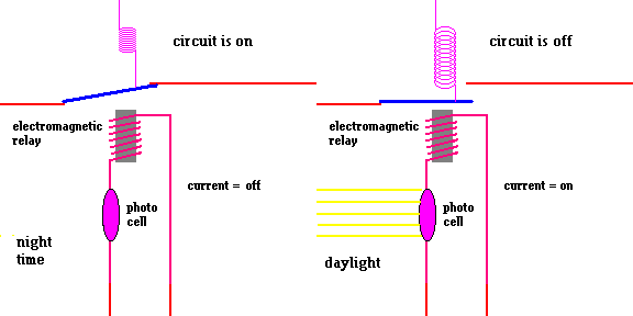
A simple night light (animation)
The photocell (cadmium sulfide photo-resistor) conducts electricity when light is shining because the resistance is very low. However, when no light shines on the photocell, the electrical resistance increases, and no current flows. A relay is used to turn on a circuit at night. In this example, the switching is done by a mechanical relay. However, most switching is actually done by using transistors. This is covered later.
Suppose a wire has a small electric current flowing through it. You already know that a magnetic field is set up around a current carrying wire. If the wire then runs through an external magnetic field, the two magnetic fields interact. In the Hall Sensor, the wire is held in place and the electrons moving through the wire itself are deflected to one side of the wire. See the animation below:
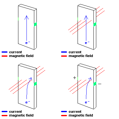
How a Hall Sensor works (animation)
Small electric contacts (shown in green) are placed on opposite sides of the wire. If there is no external magnetic field present, electrons within the wire will move in a straight line (upwards), so there is no potential difference (voltage) between the contacts at opposite sides of the wire. However, the situation is different if this wire is exposed to an external magnetic field. The external field will cause the moving electrons to deflect in one direction (say to the right). Now the right side of the wire is slightly negative and by default, the left side becomes positive. This is a voltage difference that a microcontroller can acknowledge and act on. This device is called a Hall Sensor. Essentially it is a device that can tell you if there is an external magnetic field present. Hall sensors have many practical applications.
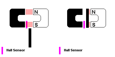
animation
One way you could use this device is to tell when a container (getting filled with a liquid) is full. Using the animation above, imagine the black (moving) metal is part of a float system. As the liquid level goes up, so does the metal strip. When the tank is full, the metal strip interrupts and redirects the magnetic field lines away from the Hall Sensor. This signal is sent to a computer to shut off the fill cycle (probably with a solenoid).
Another common application of a Hall sensor is seen on a car. When you press the brake pedal, it also moves a Hall sensor away from a magnet. This information is sent to a computer which activates a relay for the brake lights to go on.
Still not convinced that Hall sensors are practical devices? Try these applications:
Hall sensors may be used to tell how fast a shaft is spinning.
Embed a permanent magnet on the shaft and a Hall sensor adjacent to it.
Every time the shaft moves past the sensor, a computer will know it. This
is utilized in regulating the rotational speed of diskette drives, timing
devices in an engine (measuring RPM), and alerting the anti-lock system that one
of the wheels has locked up
As a position sensor it can tell you if the printer is out of
paper, your power windows are up or down, you have your seat belt on or
off. Automated assembly lines are loaded with Hall sensors to tell
computers the position of pistons, location of robotic arms, etc. You can
probably guess many places this sensor would be helpful.
How does an automatic coffee dispenser machine know when the cup is full? A flow meter has a device that spins like a water wheel. One of the blades has a magnet attached at the end which moves by the Hall sensor every rotation. A computer knows how many spins it takes to fill the cup. The computer will activate a relay that powers a solenoid to shut off the flow of coffee into the cup.
|
|
This is how the coffee machine knows when to shut off the spigot
(with a solenoid).
Since a current carrying wire will produce a magnetic field
of its own, a Hall Sensor can be used to measure the strength of that field and
thus, the amount of current in the wire itself. This is a useful and
reliable way of measuring the current in a wire without interrupting the current
itself.
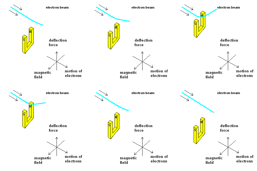
Electron deflection in an external magnetic field (animation)
Electrons moving through space are deflected in a magnetic field! This is how the beams of electrons in a cathode ray tube (CRT - like a very old computer monitor) and television tubes (link 3.3.c) are directed to exact positions on the screen by using strong electromagnets.
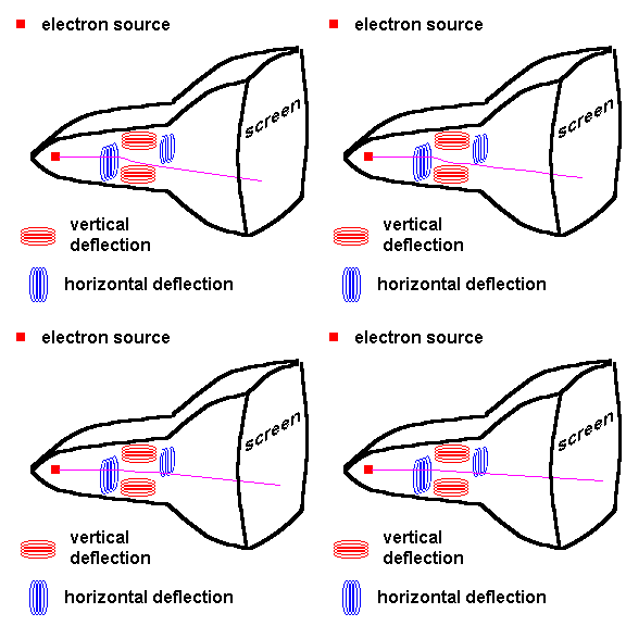
(animation)
You should be able to see why this occurs. The moving electrons that make up the beam are just like the electrons moving in a wire. If a current carrying wire generates a magnetic field, it stands to reason that a free electron moving through space would do the same. Now all you have to do is introduce an external magnetic field and it is easy to see why the electron gets deflected - magnetic forces! Note: The direction of the deflection force is perpendicular to the direction of motion and the magnetic fields lines.
If you now just go one step farther, imagine the beam of electrons (above) is now confined in a wire. You should see that the entire current carrying wire will exhibit the same force of deflection when placed in a magnetic field. This force can be put to great use to make a motor spin.
The motor has a part that spins called the armature (or rotor) and is essentially an iron bar with wires wrapped around it (which constitutes an electromagnet). Surrounding the armature is an external magnetic field (either a strong permanent magnetic or another electromagnetic) called the stator. The magnetic fields of the armature and stator interact and cause the armature to spin. The secret is to make sure the armature is always compelled to spin in one direction when you need it to.
Essence of an electric motor
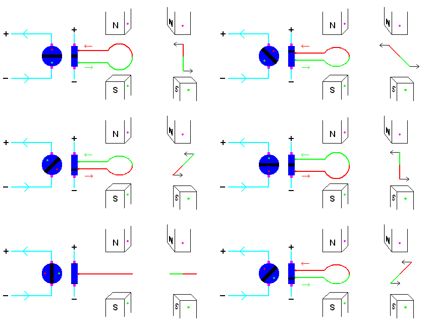
DC motor showing the commutator and side views (animation)
Please click link 3.3.d to see how a simple DC motor works. Notice the clever way this motor is able to run off DC current. A device called a commutator provides a mechanical means of switching the direction of the current fed to the rotor. Power from the battery makes physical contact with the commutator using brushes. The commutator then feeds electric power to the rotor (armature) in such a way as to produce rotation on one direction (say counterclockwise). Once the rotor makes a half rotation, it reverses the direction of the current through the rotor. Why? Consider what would happen without this device. Lacking a commutator, the wires which were providing a counterclockwise rotation would be oriented to produce a clockwise rotation one half rotation later. This would stop the rotor in a hurry. Can you see why a commutator is not necessary if the rotor is fed AC currents? How fast must a motor spin if fed conventional AC power? Note: Such a motor is called a synchronous motor because of its relation to the line frequency?
If interested, read link 3.3.e to learn more about electric motors.
When we discussed bicycles, we mentioned that the power delivered to the wheel was not continuous ... but changed from zero to some maximum value. This was because torque (and, therefore, power) is not only a function of force and lever arm but direction. That is, the torque is a maximum when the applied force is perpendicular to the lever arm and zero if applied along the direction of the pivot.
The same idea applies in the case of the motor. The voltage supplied to your house is called "single phase" ... meaning it is a single wave that changes in time like a sine wave over time. Suppose we consider a very simple DC motor. In the diagram below, the stator (stationary permanent magnet) and the coils (usually found on the rotating armature) are reversed for simplification.
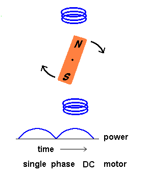
As you can see, the power delivered to the armature is not uniform. In fact, if the armature came to rest in a horizontal position, it may not be able to start the next time because there would be no torque at all to get it moving.
How do you get around these problems? One solution is to use 3 different coils where the voltage is 120 degrees out of phase to each other. This would be called a 3 phase motor. Again, the rotor is shown as a permanent magnet and the stator as the electromagnet for simplicity. In reality, the stator can be the permanent magnet and the rotor the electromagnet, but it works either way.
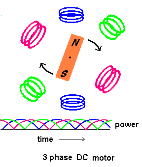
As you can see, the power delivered would be much more uniform than in the single phase motor because each coil delivers its peak torque at a different time. You don't have to worry where the rotor comes to rest because you are guaranteed that at least two of the windings will be able to deliver a starting torque. In addition, this type of motor allows precise positioning because the shaft rotates in fixed angular units (steps) when its phases are energized in a predetermined order. A variation known as a stepper motor is commonly used in computer hard drives to move the read/write heads to exact positions. The animation below shows 4 permanent electromagnets with "teeth" which, when energized, attract similar teeth on the central rotor. The electromagnets are arranged in such a way that when the teeth of electromagnet #1 are aligned to the teeth of the rotor, the teeth at electromagnet #2 are slightly offset from the rotor teeth. A microcontroller will switch off electromagnet #1 and switch on electromagnet #2. This causes the rotor to shift to a new position. The process repeats with electromagnets 3 &4.
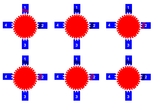
stepper motor animation
However, the most common device found in hard drives is called a voice coil motor (VCM). A coil of wires encompasses a permanent magnet. When the coil is energized, the two magnetic fields interact and the entire assembly pivots so the read/write heads move to an exact position over the disk platter.
Voice Coil Motor
Generally speaking, DC motors are used in cases where speed control is required because the speed is controlled by the voltage. Higher voltages produce faster speeds. However, most motors run off AC power.
There are several types of AC motors ... the details of which are beyond the scope of this course. The AC motors you find in your house are all single phase but industrial motors require 3 phase voltage (which can be ordered from the power company). Below are some details about two common types of AC motors.
©2001, 2004, 2007, 2009, 2016 by Jim Mihal - All rights reserved
No portion may be distributed without the expressed written permission of the author