Key Terms
aperture
compound microscope
index of refraction
fiber optics
focal length
focal point
Fresnel lens
light collecting power (of a telescope)
magnifying glass
magnifying power (of a telescope)
mirror
real image
reflection
refraction
resolving power (of a telescope)
Snell's Law
total internal reflection
virtual image
Introduction
Before we start discussing optical instruments, we first need to understand why a lens is able to "bend" light. Light travels at 186,282 miles/sec in a vacuum, but moves at a slightly slower speed when passing through transparent materials. As a result, the wave fronts are forced to change direction as seen in the animation below which demonstrates what happens when light waves pass from air to water..
Light slows down and refracts when passing from air to water (animation)
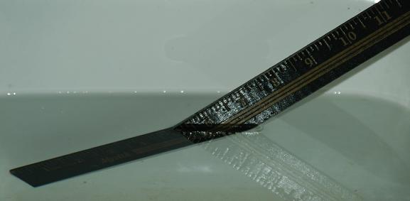
No, my yardstick is not broken!
All transparent substances are assigned a quantity known as the index of refraction (n). This quantity is calculated by computing the ratio: n = c/v; where c is the speed of light in a vacuum, and v is the velocity of light through the given material. Below are the values of (n) assigned to some materials:
| Material | Index of Refraction (n) |
| vacuum | 1.000 |
| air | 1.000277 |
| water | 1.33 |
| crown glass | 1.5 - 1.6 |
Basically, when light passes from a substance of a lower index of refraction (fast speed) to a substance with a higher index of refraction (slow speed), it bends toward the "normal" (the perpendicular line shown in black in the image below). The precise amount of refraction is given by Snell's Law (the ratio expressed in the image below).
Snells' Law
Basically, Snell's Law tells us the more light slows down at the boundary, the more it refracts or "bends". Don't worry! You won't be asked to calculate anything with this equation.
There are two kinds of images - real and virtual.
Real Images - a real image is an image you can project on a screen (movie screen).
Virtual Image - a virtual image is an image of something seen through a lens (telescope).
Examples:
| Real Image | Virtual Image |
| Movie Projector | The way you see the world through your eyes |
| Slide Projectors | Looking through a telescope |
| Overhead Projector | Looking through a microscope |
| projection TV screen | Holograms |
Since most imaging devices use lenses (or combination of lenses), let's start by understanding a simple magnifying glass (also known as a converging or convex lens).
A simple lens works because it bends (refracts) light rays.
In this example, parallel light rays enter the lens and are refracted to one point, called the focal point. This technique, called ray tracing, is helpful for understanding how different images can form using a single lens.
A magnifying glass can produce both real and virtual images, which can be demonstrated with any one of the several interactive programs listed below. Each lets you manipulate an object in a virtual environment and you can see how it alters the image. Each starts with a screen that shows a thin lens, an object (to the left), and a real image (to the right). The focal point of each lens is designated "F" or "X" and is displayed on both sides of the lens for reference.
Interactive lens (pick your favorite)
link 5.7.a (use Interpretation mode)
link 5.7.b (my favorite .. it lets you change the focal point by
changing the first two slide bars and click the box to show virtual images)
The neat thing about these programs is that they let you move the object relative to the lens. Play around with it for a while, you can reset it to the initial conditions by reloading the page. Try answering these questions (answers are at the bottom of this page).
Question 1: What happens to the image when you increase the distance between the lens and the object (move the object left ... farther from the lens)? Pay attention to how the size of the image changes, as well as the position of the image (relative to the lens).
Question 2: Where (relative to the lens) do you suppose the image is if the object is moved to an infinite distance from the lens? Note: This is not possible in these programs so you have to extrapolate.
Question 3: At what point are the object and image about the same size?
Now start moving the object closer to the lens.
Question 4: What happens to the real image (on the right side of the lens) as the lens gets closer to the object?
Finally, keep sliding the lens closer to the object until the image flips to the left side of the lens. When this happens: the image and object appear on the same side of the lens. It becomes a virtual image. To view it, you need to place your eye on the right side of the lens, ... look through it, ... and you "see" the virtual image.
The eye sees an enlarged virtual image of the object
Question 5: At what point does the image change from real (on the right side) to virtual (on the left side). That is, what is the relationship between object and lens at this critical junction?
Now you can see that you can produce both real and virtual images with a simple lens. Most optical devices use combinations of lenses to accomplish a specific task.
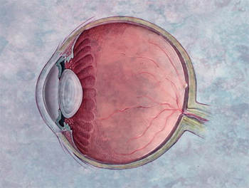
The human eye is a simple lens but with the ability to alter its focal length (by changing the thickness of the lens). The thicker the lens, the closer the focal point moves in. To see an object, a real image is projected on the retina (which is upside down). Actually the cornea is responsible for most of the refraction done in the eye (not the lens).
If interested, click link 5.7.c to see a Java applet or just use my favorite simulator listed above and change the curvature radius.
Farsightedness - the inability to focus on close objects (there is no
problem seeing distant objects).
Nearsightedness - the inability to focus on distant objects (there is no
problem seeing close objects).
If interested, click
link 5.7.d to see how glasses correct vision problems.
You already know that if you place an object between f and 2f of a lens, it will project an enlarged real image. This is the principle behind both the overhead and slide projectors.
|
Optics of a slide projector |
Overhead Projectors use a Fresnel lens for backlighting |
The overhead projector uses a lens (at the top) to convert a slide transparency into a real image (on a screen). However, it needs nearly parallel rays of light moving through your transparency which acts as backlighting. To accomplish this, a special kind of flat lens, known as a Fresnel lens, is used. How can a flat surface refract light? I hope the image below helps solve the mystery. The lens is not really flat, but holds the same contour as a normal convex lens, only as small adjacent "steps" (as seen below). It does the same things as the full lens, and appears nearly flat.
An intense light bulb is placed at the focal point of this Fresnel lens and as a result, light rays move through the transparency nearly parallel. The lens at the top of the overhead projector is the real workhorse here, converting these rays to a real image on a screen.
How a SLR (single lens reflex) camera takes a picture (animation)
Once you understand how a slide projector works, it is easy to see how a camera works as well. A real image must be projected on the plane of the film or CMOS image sensor (digital camera). A focus controller is used to complete this task. This is accomplished manually by moving the lens in or out until a sharp image appears in the viewfinder. Auto focus cameras use sound waves or infrared light to reflect off the subject and back to the camera. The travel time is converted to a distance in a technique called echolocation. Once made, the camera adjusts the lens position with a piezoelectric or electromagnetic stepper motor.
Cameras also adjust the amount of light striking the focal plane by adjusting the aperture. This is similar to the way the iris of your eye opens or closes to expose the pupil to more or less light. The aperture also dictates the "depth of field". The "depth of field" is the range your subjects can be from the camera and still be in focus. A smaller aperture may let in less light, but gives a wider depth of field.
|
How to control light and "depth of field" (animation) |
I had the aperture open too much in this picture. The result was a narrow depth of field. |
You already know that a simple magnifying glass can produce enlarged virtual images. This is the simplest kind of microscope you can make. A compound microscope uses 2 or more lenses to produce very large virtual images.
The object you are trying to view is placed just outside the focal point of the objective lens (on the left). This produces a large real image. An eyepiece (shown on the right) is then used to further enlarge this real image. As long as this real image is inside the focal point of the eyepiece lens, it will produce an even larger virtual image.
A very simple optical device is a telescope. All you need is two
converging lenses with different focal lengths. The collecting lens
(called the objective) must have a much longer focal length than the eyepiece
lens. Usually, a telescope is focused at infinity where a real image
appears at the focal point. If the object of interest is relatively close, the real image does not appear exactly at the focal point, and an
adjustment in focus is required. When looking through a simple
refracting telescope, the image is inverted. This is not a problem
unless you use the telescope to look through neighbors windows (naughty
naughty)! Eyepieces
which will invert the image are available.
A simple refracting telescope
The formula for magnifying power (M) is:

where fo is the focal length of the objective (light collector) and fe is the focal length of the eyepiece. Since the focal length of the light collector is fixed, you change magnification by swapping eyepieces. The eyepiece with the lower focal length gives a higher magnification. Surprisingly, telescopes are NOT typically designed to offer extremely high magnifications. Most things in the sky are inherently dim. A much greater need is light collecting power, which is controlled by the diameter of the objective lens. The bigger the light bucket, the brighter the image. In fact, the magnification of the image also affects how much light is concentrated over the viewing area. A lower magnification produces a more intense image. A third factor, called resolving power, dictates whether 2 separate but close objects appear as distinct light sources, or only one. This is also determined by the diameter of the objective. The larger the lens, the better the resolution becomes.

Since a telescope is designed to capture very faint light and produce highly resolved virtual images, a large diameter objective is preferred. Making large lenses is very expensive. To reduce costs, astronomers use a curved (parabolic) mirror to accomplish the same task. A telescope which uses a mirror to collect and focus light is called a reflecting telescope.
Two popular designs are the Newtonian Reflector and the Schmidt-Cassegrain Telescope.
The
Newtonian Reflecting Telescope (link
5.7.e)
A
Schmidt-Cassegrain Telescope (link
5.7.f)
We have seen that a mirror can replace a lens in a telescope. The fact that a mirror can bring light to a focus point makes it the perfect tool for "capturing" other types of radiation. Astronomers use radio telescopes to concentrate faint radio signals from space to a focal point where it is picked up by a receiver.
 |
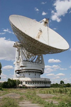 |
A parabolic mirror will focus radiation
Radio telescope Courtesy
Wikimedia Commons
If you have Direct TV® or Dish Network®, you have a radio receiver that works on the same principle.
A flashlight is a radio dish in reverse. The light bulb is placed at
the focal point and light is reflected out to space by the curved mirror.

A flashlight or headlight (animation)
Texas Instruments has developed a digital light processor or DLP (link 5.7.g) for home high definition projection screens. The DLP is essentially an array of tiny mirrors on cantilevers that are controlled by electrical impulses (to move the mirror via piezoelectric or electrostatic actuators). These mirrors are able to move thousands of times every second. Light from a central source hits the mirrors and (depending on the mirror position) hits or misses the target screen. To see color, the light passes through a filter in the form of a rotating color wheel. This technology was developed 20 years ago- well before HD displays were common accessories in homes nationwide.
DLP animation
Consider a ray of light as it moves from a boundary of glass fiber and the air. When the light ray meets the boundary, some of the light will refract out into the air, and some will be reflected back into the glass fiber (and a very little will be absorbed by the glass itself). See the animation below. As the angle of incidence increases, the refracted beam is directed progressively farther from the normal (perpendicular). Eventually the system reaches a point (a critical angle) where no light can possibly refract out into the air ... leaving only reflected light. This is called total internal reflection and is the key to understanding fiber optics.
How fiber optics works (animation)
Click link 5.7.h to view an interactive program (move the green dot) which shows how light beams reflect and refract (bend) as they go from one medium to another. Notice that at a certain angle, there is only reflected beams.
Laser beams can be used to transmit signals for very long distances (2014 record of 7,400 miles - link 5.7.i ) and engineers are finding ways to cram more and more signals through fiber optics cables without loss of data. They do this by sending individual data signals across at different frequencies. Can you believe we are talking up to several terabits worth of data per second (depending on the distance)??? Now that is a lot of bandwidth!!! But don't get too excited if your cable company offers a fiber optics network. Most likely that only runs to the local node ... and the rest is coax going to your home.
One easy and inexpensive way to pinpoint the location of an object is to let light from a fiber optics system bounce off the object (actually a mirror attached to it). If the mirror is relatively close to the end of the cable, most of the light will reflect off the mirror and go right back into the cable (which is monitored with a photo sensor). As the mirror moves farther away from the end of the cable, less and less light will be reflected back into the cable, so the reflected intensity of the beam drops.
Fiber optics location sensor (animation)
If interested, click
link 5.7.j
to learn more about fiber optics
©2001, 2004, 2007, 2009, 2016 by Jim Mihal - All rights reserved
No portion may be distributed without the expressed written permission of the author
Answer #1: The farther the object is moved from the lens, the closer the image moves to lens. At the same time, the image gets smaller.
Answer #2: When the object is at infinity, the real image is the closest it can get to the lens - the focal point.
Answer #3: If the object is at 2F (twice the focal length), the image and object have the same size. The image is also at 2F.
Answer #4: As the object comes closer to the focal point, the image gets larger and appears farther from the lens.
Answer #5: Once the object moves inside the focal length of the lens, the image becomes virtual. The virtual image is largest when it is just inside the focal point and becomes smaller the closer it gets to a lens. This is what you are doing when you use a magnifying glass. If you have one around the house, play with it just like the interactive programs. As a kid, you may have used it on sunny days to burn leaves or wood. The sun is essentially at infinity, you were making a real image of the sun. You were also discovering the focal length of the magnifying glass.