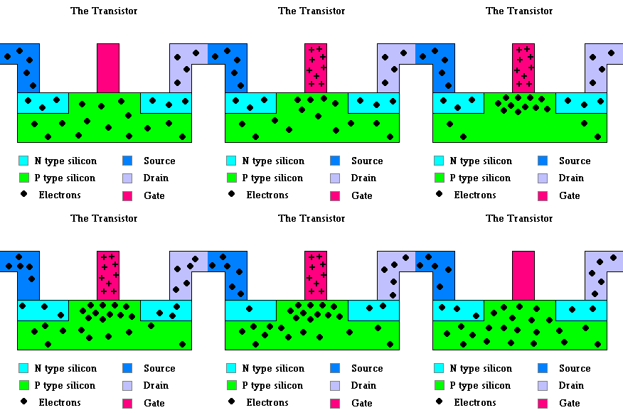
Essence of a transistor (animation)
Transistors (and Microcontrollers)
Key Terms
microcontroller
transistor
Some call the transistor the greatest invention of the 20th century. It is an electrical switch and signal amplifier that made desktop computers and microcontrollers a reality.

Essence of a transistor (animation)
A transistor consists of materials called semiconductors. Semiconductors have the properties that they can act as insulators at one time and electrical conductors at other times. These materials are made of silicon and are at the heart of all computer chips. Please review the unit on photovoltaics to see how the electrical properties of silicon change when doped with impurities and how charged particles behave at n-p junctions. Recall that the n-p junction forms a diode ... a one way check valve for electricity.
The image above is a transistor known as an n-p-n transistor. Normally current cannot flow from source and the drain (electrical inputs and outputs) because it is blocked by diodes in both directions. That is, there is an n-p junction in both directions. That can all change, however, when a small positive voltage is applied to the gate (as shown in the top center of the above diagram). When this happens the "p type" silicon acts as an electrical conductor allowing current to flow from the source to the drain. Essentially the gate attracts free electrons and renders the n-p junctions useless as diodes. Granted, this is an over-simplified version of a transistor (from a physics point of view) ... but the concepts are valid and important for understanding how many devices (including computers) work.
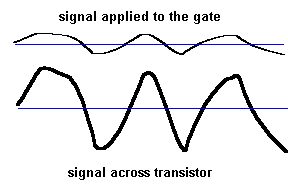
How many times have you seen different ways of switching things on and off in this class? A transistor is the granddaddy of them all. When a small voltage is applied to the gate, it acts like a switch and allows current to flow between the source and the drain. As a bonus, the transistor can also act as an amplifier. A small charge on the gate only allows some current to flow between source and drain. A bigger charge on the gate lets more current pass. With this property, a small (varying) electric pattern applied at the gate constantly changes the amount of electric resistance across the transistor (between the source and drain) ... this makes possible a similar but much larger electric signal across the transistor.

Allow me to offer an analogy. Suppose you were in charge of manning a flood gate at a dam. Suppose it takes a small effort to open and close this gate. However, the power in the rushing water you allow can be enormous. If you expend almost no effort and the gate is only 10% open, then only 10% of the maximum amount water can flow. If, however, you put in a bit more effort and open the gate 50%, then you get a corresponding increase in water flow. Go all out and open the gate completely and huge volumes of water rush past. The point is that the pattern of effort you apply to the gate is matched by a pattern of water flow ... and there is a lot more energy in the water than there is in your gate control.
Transistors act as the heart of all amplifiers ... where a weak electric signal is boosted to drive huge speakers. It is also a great switching device ... you know ... on/off. The first computers used mechanical electromagnetic relays to act as switching devices. These are very easy to understand but extremely slow. Vacuum tubes replaced the electromagnetic relay and made computers work 1000 times faster. But vacuum tubes were big, produced a lot of wasted heat, used a lot of electricity, and broke down often. The transistor replaced the vacuum tubes and made desktop computers a reality because they were very small, produced almost no heat, used very little electricity, and were very reliable. Today, nearly all on/off switching in electrical systems is done by transistors.
Let me give just one example to demonstrate where the application of transistors (as switching devices) is commonly seen. We have already seen how dimmer switches can be constructed using a variable resistor (rheostat). However, this produces a lot of waste heat since the rheostat is placed in series with the light bulb. That is, if the lights are turned down, then the rheostat is set to offer the most resistance (which makes waste heat) ... not exactly an energy saving strategy. A better way is to use a much smaller amount of electricity at the gate of a transistor to control the (much larger) current directed toward the light bulb. Here is how it works:
Normal line current is 120 volts AC which cycles itself 60 times each second. The voltage, however, is constantly changing with time (image below). If you can "chop up" this cycle so you are only using it part of the time, the total amount of energy used by the light bulb will be less and the light will become dimmer. A rheostat linked to the gate of a transistor now decides when the switching occurs (basically it decides how long it will take to charge up a capacitor ... which feeds the gate).
|
|
|
The system is designed so that the transistor is always switched "off" whenever the line voltage reaches zero (the beginning and middle of each cycle). The "on" is decided by the setting at the dimmer switch. By turning the dimmer knob, you decide what part of the normal electric cycle you wish to turn juice "on" to the light bulb. You must agree that no human could switch things on and off this fast ... but, this is no problem for a transistor.
If interested, read
link 4.4.a article about transistors or
link
4.4.b
to see another article about transistors.
Computer chips can have programmed instructions "stamped" on them. For example, the ROM chip in a computer has all the start-up instructions frozen in the design. These instructions never change, so there is no need to make use of RAM memory (memory that changes depending on the application). Most devices that perform only one specific task can make use of this same technology. A single chip can be designed to carry out one "program" because the device only does one thing. These chips are known as microcontrollers ... and these chips are almost everywhere! Transistors make microcontrollers possible because part of their magic requires lightning fast switches.
A control engineer specializes in designing systems that do only one task. This is not only important in assembly line manufacturing but also in the chip designs for most electronic applications.
The engineer designs sensors which convert some information (input) about the real world (temperature, location, force, etc.) to an electric signal. The microcontroller then manipulates the signal (using programs) and produces another electric signal as output. Finally, an actuator uses the output signal to make something happen. The output can take many forms ... a signal to a speaker ... a command to turn something else on ... display digital letters ... etc.
Here are some examples:
Digital thermometers ... the kind you see at the doctor’s office...
An electronic thermostat (in your home) will take in the same input signal but, ...
A simple bicycle speedometer ... when you pedal your bike ...
An electronic water softener...
Don't worry if we haven't covered how these chips carry out instructions. It is very technical and well beyond the scope of this class. However, we will offer a taste of how this is accomplished in the last unit when we discuss computers.
©2001, 2004, 2007, 2009, 2016 by Jim Mihal - All rights reserved
No portion may be distributed without the expressed written permission of the author