Key Terms
amplitude modulation (AM)
frequency
frequency modulation (FM)
microwave oven
peak detector
tank circuit
wave modulation
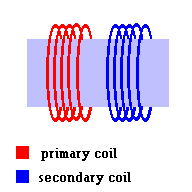
Think back to unit 3 when we covered induction. If you recall, a transformer consisted of two separated coils of wire. You learned that you can induce currents to flow in one coil (blue secondary coil) as long as it was surrounded by a changing magnetic field. To produce that changing magnetic field, you could run a changing electric field in a nearby coil (red primary coil) ... either in the form of DC pulses or steady AC currents (just as long as it was a changing electric field). The primary and secondary coils never touch and the iron bar was only used to concentrate the fields to improve efficiency. It would still work without an iron bar. At the time, you probably never thought that the two coils were talking to each other using electromagnetic radiation ... likely low frequency radio waves. In this section, you will see that you can also imprint a message that can be conveyed from one coil to the other. The red coil becomes the transmitter and the blue coil becomes the receiver.

We already know that light is a wave (called electromagnetic radiation), but let's gain a better understanding of the exact nature of this type of radiation. It consists of an oscillating electric and magnetic field that travels through space as a transverse wave. We also know that one way to distinguish waves within the electromagnetic spectrum (visible, infrared, microwaves, etc.) is by differences in wavelength.

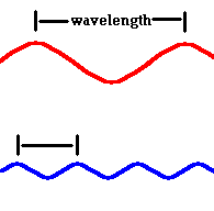
Red light (at one end of the visible spectrum) has a longer wavelength than blue light. However, another way of distinguishing between different colors of light is by their frequency, the number of waves that pass by a point every second. It seems odd that we generally classify sound waves by differences in their frequency and electromagnetic waves by differences in their wavelength. The fact is, you can use either label because they are related by the formula: v=fλ where v = speed, f = frequency, λ = wavelength. In the case of electromagnetic waves:

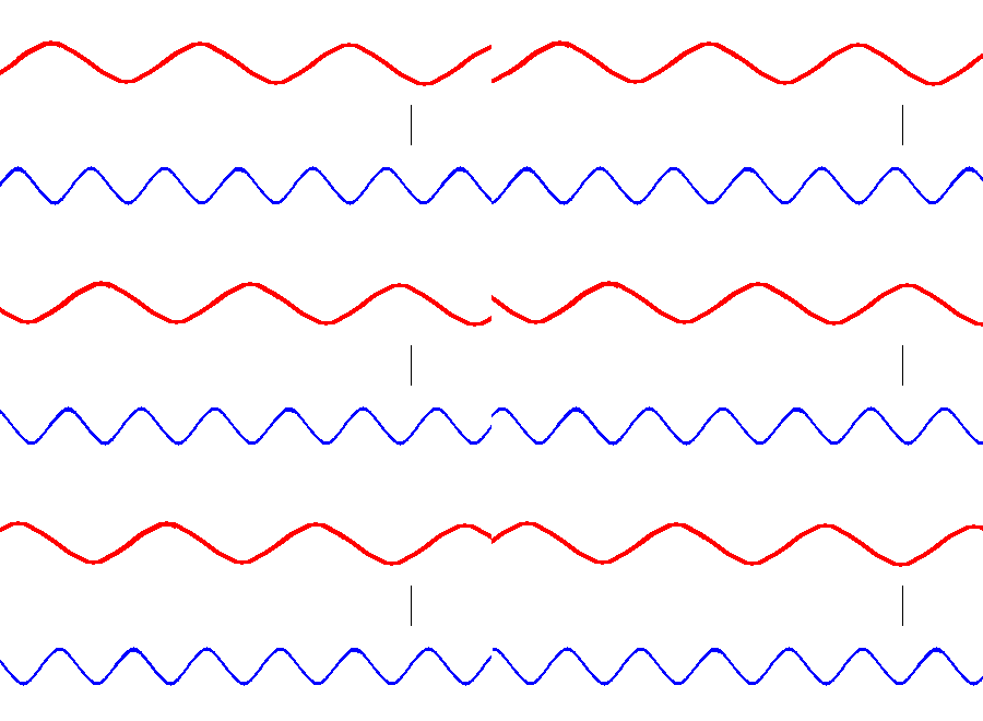
Red light has a lower frequency than blue light. (animation).
The animation above is designed to show that red light has a lower frequency than blue light. However, there are waves with higher frequencies than blue light and waves with lower frequencies than red light. These radiations are invisible to the eye, but exist in nature. Together they form the electromagnetic spectrum.
| Wave type | Wavelength Range | Frequency (all these numbers are BIG) |
| radio | >1 meter all the way to hundreds of km | Hz - GHz 1 - 109 Hz |
| microwaves | ||
| infrared | ||
| visible | .0007 mm (red) to .0004 mm (violet) - this is actually a VERY small slice of the pie | |
| ultraviolet | ||
| x rays | .01 - 10 nm (nanometers ... a billionth of a meter 10-9) A hydrogen atom has a diameter of about 10 nm |
|
| gamma rays | typically smaller than an atom - 1-100 pm (picometer 10-12) | EHz - 1018 Hz (a very big number) |
Example: Calculate the frequency of violet light. Answer: The only trick is to use standard units. c = 300,000,000 m/s, λ = .0000004 m f= c/λ = 300,000,000/.0000004 = 750,000,000,000,000 = 750 x 1012 Hz = 750 THz (terahertz). Don't worry, I won't ask this on a test.
James Clerk Maxwell (1831-1879) was the person who solved the mystery of light. Before Maxwell no one really understood the nature of this wave. The term electromagnetic should tell you that electricity and magnetism play important roles in the story. Perhaps the best place to start is by having a charged particle oscillate in space and see what happens next.
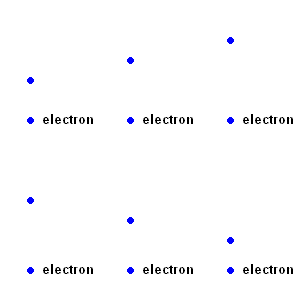
EM waves have to start somewhere (animation)
Any charged particle has a surrounding electric field associated with it. This, theoretically, extends through space without end (just as all masses have a gravitational field associated with them). In fact, physicists tend to concentrate on the electric fields surrounding the charged particles (and not so much on the particles themselves). When the particle moves, the surrounding electric field changes with time! That is, if the charged particle oscillates, its motion produces a "ripple" in the associated electric field.
|
|
|
Maxwell connected electricity with magnetism when he said: A magnetic field is induced in any region of space where an electric field is changing with time. The magnetic field forms at right angles to the electric field. The strength of this magnetic field depends on the rate at which the electric field changes.
Let’s go back to the "ripple" in the electric field. Maxwell says there has to be a magnetic field produced as a result of it. The magnetic field grows as the electric field grows, and shrinks as the electric field shrinks. Remember the unit on induction? We learned that current is induced in a wire surrounded by a changing magnetic field. More appropriately, an electric field is induced in any region of space where a magnetic field is changing with time. (In the case of induction, it is this electric field that exerts the forces on nearby electrons and compels them to move as electric current.) In addition, the electric field forms at right angles to the magnetic field. The strength of this electric field depends on the rate at which the magnetic field changes.
But wait! This changing magnetic field will now induce a changing electric field ... which induces another changing magnetic field. There is no way out! This electric - magnetic game of leap frog continues through space as a wave we call electromagnetic radiation.
|
|
Making an electromagnetic wave (animation) |
The exact type of electromagnetic radiation we get (radio, microwaves, etc.) really depends on the frequency of the original oscillating electron! A radio transmitter, for example, is made to emit radio waves as electrons oscillate in an antenna with just the right frequency.
The key is that EM waves are produced when a charged particle oscillates.
One way we can use the energy of electromagnetic waves as they pass by is in the microwave oven. The actual heating of the food results from the vibrations of water molecules within the food itself. Microwave ovens generate electromagnetic energy with a frequency of about 2.45 GHz (2,450,000,000 waves per second). Water molecules react to the electromagnetic radiation because it is a polar molecule. The overall charge on the molecule is still zero, but within the molecule, the charges are not distributed evenly. That is, it has net electric charges at the ends of each molecule. Each hydrogen atom has a net +1 charge, and the oxygen atom has a net -2 charge.
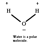
Normally, the water molecules in your food are randomly oriented. However, when an external electromagnetic field is applied ...the molecules tend to "line up" with the applied electric field. As the electric field changes directions, the water molecules realign themselves with the field by flipping around 180 degrees. This motion is quickly transferred to adjacent molecules in the form of heat (random motion of molecules).
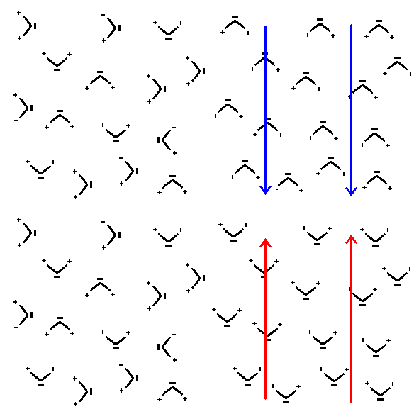
Water molecules flip when an electric
field is applied. (animation)
Wireless communication has been around since the early part of the 1900's. Today, we
send and receive signals from powerful antennas (radio and TV), satellites
(DirecTV® , Dish Network® or HughesNet®), remote control units, cell phones, computers (infrared links),
etc. All these devices imprint a message on electromagnetic radiation
(usually radio waves).
The basic steps covered below are:
Please see the section (above) on James Clerk Maxwell. Oscillating
charges make electromagnetic waves.
The key to placing a message on an electromagnetic wave comes from an idea that waves can be added together to produce a new wave. This is nothing more than an application of the Principle of Wave Superposition ...something we discussed earlier. This is how a "carrier wave" is modulated to encode a voice signal.
More specifically, a smaller wave can be encoded on a larger wave. The image below gives an example with "square" waves because it is both easier to see and much easier to draw. In the real world, the waves are sine waves.
A message is "coded" on an electromagnetic signal by "modulating" either the amplitude (AM ... amplitude modulation) or frequency (FM ... frequency modulation).
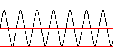
An "un-modulated" carrier wave shown in black is combined with, ...
... this signal of the music you want to hear (blue wave) to make ...
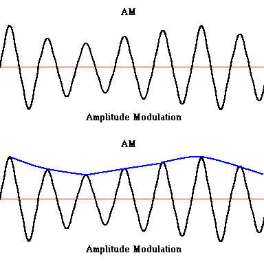
... this modulated wave. Not drawn for accuracy. (animation)
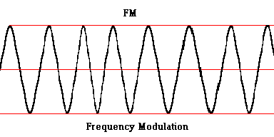
You can also modulate the wave by changing the frequency. Notice slight shifts in the wavelength? This is how FM radio works.
At the radio station, an antenna is used to broadcast the modulated wave. This is done by oscillations of electrons (AC currents) within the antenna. This complex oscillating pattern then produces the electromagnetic signal that travels out through space (to your receiver).
At the receiving end, a radio antenna intercepts the transmitted wave and starts oscillating. The animation below demonstrates how an electromagnetic wave can set a free electron into convulsions.
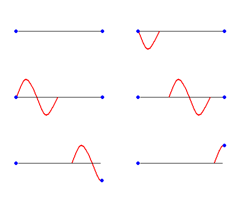
Oscillations ... to EM waves ... back to oscillations (animation)
The problem here is that the free electrons are oscillating in an extremely complex pattern. You see, there are many radio stations and each one is sending out a modulated wave. The free electrons are affected by each of these waves.
At the receiving end of the radio signal, the antenna is connected to an oscillator which uses a variable capacitor and an inductor (electromagnet) to "tune" to one specific frequency of radio wave. This is sometimes called a "tank circuit".
You can think of this tank circuit as a "filter" which is used to isolate the carrier wave you want to pick up (the radio station you want to hear) from all the other radio stations in the area. As an analogy, think of a simple pendulum where the bob swings and converts potential energy to kinetic energy and then back to potential energy again. The "tuner" is the length of the string. A long string will make the system oscillate with a low frequency (it takes more time to swing), but if you shorten the string, the bob takes less time to swing ... shortening the frequency. The tank circuit works the same way. An electric signal will bounce between the capacitor (where it is charged up and then discharges) and inductor (remember the metal detector? A pulse goes in and a "back emf" comes out). A returned signal is sent back to the capacitor ...and the process repeats. Just as the pendulum is constantly converting energy from potential to kinetic and back to potential, ... the tank circuit converts energy from an electrical field (in the capacitor) to a magnetic field (in the inductor) and back to an electrical field. It takes a certain amount of time to complete the cycle, so only one frequency of AC current is allowed to "oscillate" in this manner. That is, the circuitry is adjusted so that only one specific type of wave will resonate within it. This is how the tank circuit works to only let one wave through ...the one tuned to your radio station. If you move the channel tuner, you are changing the properties of the capacitor ... giving it more (or less) time to charge and discharge. This means a carrier wave with a different frequency (from another radio station) will oscillate in the tank circuit.
Let's take the pendulum analogy one step farther. A simple playground swing-set is nothing more than a pendulum. All kids know that gentle pushes at the right time can provide for a great ride. Think of the pushes as the input energy into your swing-set "tank circuit". For any given swing, there is only one frequency of pushes that will work for that particular swing. If the incoming energy is timed perfectly and comes in at the right part of the oscillation, you can set your swing-set "tank circuit" into resonance. In the case of the radio tank circuit, the input energy are radio waves of all kinds of frequencies (all the radio stations in town), but only one specific frequency is able to oscillate in resonance in your tank circuit.
Click
link 6.3.a to see a Java radio tuner applet. When you play with
this applet, you will see that only one specific wave frequency will "oscillate"
in the tank circuit.
Click
link 6.3.b to see a Java variable capacitor applet.
Click
link 6.3.c to read how an oscillator works.
Finally the radio must "decode" the signal by extracting the modulated signal imprinted on it. That is, you need a way to eliminate the carrier wave and only allow the original voice signal to the speakers. In AM transmission this can be done with a diode, capacitor, and resistor. A simple diode will extract only half of the sine wave. This process, called rectification, essentially converts the AC signal to a DC signal.

modulated wave before it enters the diode (black wave only -
animation)
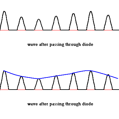
Signal after it passes through the "peak detector"
This DC signal is then sent through a capacitor. The circuit looks like this:
This arrangement is sometimes called a "peak detector" because it only detects the peak voltage of any signal. Essentially it filters out the smaller carrier wave. The reasoning goes something like this (in case you are interested ... but not required for this class). DC currents do not normally pass through capacitors very well. They will charge to the peak voltage and then block the passage of current after that. The system is designed so that there is a very slow discharge through the resistor, so the system is only sensitive to "long term" variations in the signal, and the carrier wave (which changes much quicker) is ignored. What you end up with is a signal which is a copy of the original voice or music from your favorite pop star. This signal is then sent to an amplifier and then to your speakers.
You can see that the basic components of an AM radio are actually quite simple (although the theory behind it might not be so simple). As a child, I was fascinated that I was able to listen to AM radio on my "crystal radio" set I was able to construct out of discarded electronic components. I often wondered, as a kid, how it all worked without the aid of a battery (we didn't have an amplifier attached). The energy in the electromagnetic wave was all that was needed to induce electrons to flow in the circuitry of my radio. This video does a great job putting all the pieces together using a crystal radio but don't get hung up on all the lingo ... just try to filter that out and get the concepts. Link 6.3.d
If interested, click link 6.3.e to read how radios work.
Once you understand the principles involved, you can apply it to any wireless application. This can include anything from your remote control for the TV, Bluetooth® devices, wireless internet, satellite TV, any RF (radio frequency) application, cell phone technology, etc. The key is to place information on an electromagnetic wave (by wave modulation) and find a way to separate the information from the wave at the receiving end.
Care to indulge into some futuristic ideas? How about realizing Nicola Tesla's unfulfilled dream of wireless transmission of electricity? The brains at MIT are working on a way to do away with electric power outlets in the home altogether using some of the ideas we presented here. Let's look again at that "tank circuit" we just discussed. This is essentially just a capacitor linked to an inductor (metal bar with coils wrapped around it). As the capacitor discharges, it sends electric energy through the coil ... building a magnetic field. This induces blasts of "eddy currents" to flow in the metal bar. These eddy currents (in the bar) also produce changing magnetic fields of their own ... which induce currents to flow back in the coil. These currents then flow to the capacitor and charge them up. Then the capacitor discharges, and the process repeats. Now think about this for a while ... wouldn't this "tank circuit" also be putting out electromagnetic waves at the same time during this cycle? Yes, because all you need to make EM waves is to have charged particles oscillate (which is certainly the case here). To keep the "tank circuit" humming, you would need to keep pumping energy into the system at the correct frequency, but electromagnetic waves would be moving out of the tank and through space with the same frequency. Now all you need to do is to place an identical "tank circuit #2" in a position to capture these EM waves and what happens? Just as the case with the radio, the waves are captured by tank #2 and set into resonance (much like one tuning fork will force an identical tuning fork to vibrate). Anyone interested could tap and use the currents that are now in the coils of tank #2. Wow - wireless transmission of electric power! The bad news is that this technology is only demonstrated over short distances, but maybe just as important, you are using energy in tank #1 even if you are not tapping it at tank #2. Hey, you are doing the same thing when you plug in one of those black transformers into a socket even if it is not plugged into any device for recharging!!! Touch one with your hand. It is warm because currents flow in the primary coils as long as it is plugged in to the socket. This "waste" issue will have to be addressed before we see wireless power transmission in the home.
©2001, 2004, 2007, 2009, 2016 by Jim Mihal - All rights reserved
No portion may be distributed without the expressed written permission of the author