In this animation the strength of the magnetic field changes with time (animation).
Key Terms
eddy currents
Faraday-Henry Law
generator
inductors
transformer
Around 1830, Michael Faraday and Joseph Henry independently discovered the phenomena known as electromagnetic induction. They discovered that you could induce currents to move in a wire under specific conditions in a magnetic field.
In this animation the strength of the magnetic field changes with time (animation).
They found that current will flow in a closed loop of wire provided that wire was surrounded by a magnetic field. This is known as the Faraday-Henry Law. Electromagnetic induction is the working principle behind the electric generator and power transformers ... things we cover in this section.
In fact, an electric current can be induced in a wire (in a closed circuit) by simply moving it across the magnetic field.
In this animation the wire moves through a steady magnetic field (animation).
In this example, a wire (which must be part of a closed circuit) is moved past a magnet. In the process of moving, an induced current is set up in the wire. When the wire stops moving, the current stops.
The key is, you can induce currents to flow in a wire if:
However, if a wire simply rests in a fixed magnetic field ... nothing happens!
Click
link 3.4.a to see a Java applet.
Click
link 3.4.b to see another Java applet.
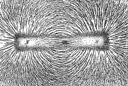
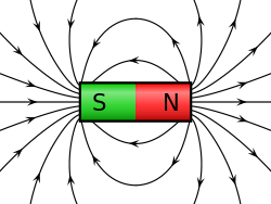
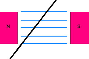
The idea goes something like this: Each magnet has field lines (or flux lines) that extend into space. These lines connect the north (N) pole of the magnet to the south (S) pole of the same magnet. You may have seen a grade school demonstration where metal filings are sprinkled near a magnet to show this effect (see image below).
|
Courtesy Wikimedia Commons
|
Courtesy Wikimedia Commons
|
If a wire is moved so it "cuts across" these lines, the free electrons in the wire receive a "push" which compels them to move. That constitutes an electric current. You should see that you will get the same effect if the wire is stationary and the magnetic field gets stronger or weaker. Either way, magnetic field lines "cut across" the wire.
Example 1 - Electric guitars work on the principles of induction. Just under each guitar string rests a small magnet. As the guitar string vibrates, it alters the magnetic field around the magnet (making field lines wiggle in space). A coil of wire wrapped around the magnet senses these changes in the magnetic field ... and currents of electricity are induced to flow in them. This signal is sent to an amplifier. Rock on, dude!
Example 2 - Have you ever wondered how those tiny odometers and speedometers work on a bike? Attached to the wheel is a permanent magnet and along the frame a tiny coil of wire is mounted so every time the wheel spins, the coil moves past the magnet. This induces tiny electric currents which are read by a microcontroller ... which converts the timing of the pulses to a bicycle speed (the odometer first needs to know the size of the bicycle tire to calibrate it). The same principle may be used in your car to determine its speed if your car has a digital odometer.
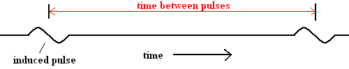
For example, suppose the time between pulses is .4 seconds on a 27" diameter bicycle tire (the wheel revolves every .4 seconds). A simple conversion shows that this bike is moving at 12 mph (don't worry if you can't do the math, a microcontroller can do it easily). Note: a Hall sensor (covered in the last unit) could also be used to do the same thing.
Example 3 - Consider the two animations below. In the first case, the magnet moves through the coils at a slow speed, and the resulting induced current is low. However, if the magnet moves quickly through the coil, the induced current in the coil is much higher.
|
|
|
Slow moving magnet (animation) Fast moving magnet (animation)
Since the magnitude of induced current depends on the speed of the moving magnet, this arrangement is a useful tool to determine the speed of any moving object. All an engineer needs to do is make sure the moving object has a magnet attached to it, and the magnet is in position to induce currents in a coil of wires.
The systems below look strikingly similar to motors introduced in the last section. They should! An electrical generator is an electric motor turned backwards. This is similar to the discussion of the water wheel and the pump. As you recall, in the case of a water wheel, the wheel receives energy from the falling water and therefore starts turning. The pump also has a wheel but in this case, the spinning wheel delivers energy to the fluids ... creating pressure differences and making the water flow. An electric motor (like the water wheel) has an armature which is compelled to spin when current is fed through a wire, and its corresponding magnetic field interacts with a permanent magnet. An electric generator (like the water pump) has an armature which, when forced to spin in a magnetic field, will induce currents to flow through the wire. In other words:
A motor converts electrical energy to rotational kinetic energy ... a generator converts rotational kinetic energy to electrical energy!
The idea is simple ... you can make current flow in a wire provided the wire is in a changing magnetic field. The spinning armature "sees" the permanent external magnets as a changing field, so current is induced in the wires of the armature. Thank you, Michael Faraday and Joseph Henry.
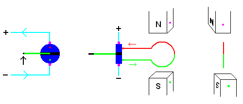
AC Gernerators
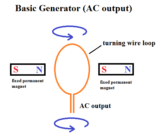
The image below shows a simple AC generator. As the armature (loop of wire) is forced to spin within the external magnetic field, current is induced to flow within the wire. However, when the armature rotates 180 degrees, the direction of the current reverses .... creating AC (alternating currents).
A simple AC generator.
Click link 3.4.c for a great demonstration
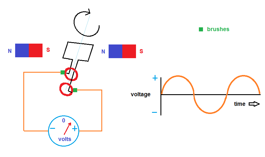
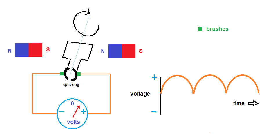
DC Generators
A DC (direct current) generator works much the same way but needs a bit of a tweak. How do you prevent the currents from reversing direction when the armature rotates 180 degrees??? Simple ... design a switch in the system. This switch takes the form of a split ring which acts a commutator. Brushes (which remain stationary) keep electrical contact with the spinning commutator. When the armature makes a 180 degree spin, this switch automatically keeps the current moving in the same direction.
DC generator (animation)
Click
link 3.4.d to see a Java applet of an AC generator and click
link 3.4.e to see a Java applet of a DC generator. Click
link3.4.f
for a demonstration of both AC and DC generators
As a kid I was given a small generator that attached to my bike. By flipping a lever, a metal cylinder would make physical contact with the wheel. When riding the bike, friction with the wheel would force the cylinder to spin and a light would shine. No batteries! I was amazed (and hooked on physics ever since). Your car has an alternator which is powered by a fan belt connected to your engine. As long as your car is running, you have all the electricity you need to control everything (including enough to charge the battery for the next time you start the car). Note: The alternator's output is AC, but since the car runs off DC, this power needs to be converted (opposite of an inverter). Older cars used generators which worked on the same principle, but had a DC output.
Electricity in your lawnmower is produced by a magneto (link 3.4.g). You can find a magneto in most gas powered lawn tools - like chain saws and weed eaters. The magneto provides the electricity used for the spark plugs. There is a very strong magnet attached to the flywheel of the engine. Every time you need electricity for the spark plug, the magnet spins past the magneto which is permanently attached to the frame. This device consists of a coil of "primary" wires. As you know, when the magnet moves past these wires, current is induced in these wires (Faraday - Henry law). However, the voltage in these wires is much too low to arc the spark plugs so another step is needed. You won't have to wait long. A discussion of transformers is just around the corner.
The electricity generated by power plants in the US is 60 Hz AC ... meaning the current goes through 60 "cycles" of flip-flops each second. The "mean" voltage is 110 - 120 volts. WE Energies supplies the Milwaukee area with electricity. They have huge generators that need to be spun by some external source. The Oak Creek power plant burns coal to produce high pressure steam. This moves through a turbine (just like water turns a water wheel). The Point Beach power plant produces the steam with the heat given off a nuclear reactor. However, the cheapest and cleanest way to spin a wheel is to use hydroelectric power ... which is renewable. Unfortunately, only the Pacific Northwest area (Washington and Oregon) has sufficient rainfall and terrain (to dam large quantities of water) which means that hydroelectric power only becomes feasible in that region.
The power to your house is 110-120 volt AC. Not all devices can make use of electricity in this form. Many devices in the home call for low voltage (AC or DC) current to run properly. In another example, the spark plugs in your car require voltages in the range of 30,000-40,000 volts but your battery is only 12 volts. Transformers make all this possible. Most homes have these tiny black boxes you plug into the wall to convert the power ... these are transformers ... so is the ignition coil in your car.
![]()
I'll bet you have many transformers like this in your house!
Transformers make use of the Faraday-Henry Law. A transformer has two sets of wires, the primary coil and the secondary coil. The two sets of coils (primary and secondary) are in close proximity to each other (but not physically connected). Both coils are usually wrapped around an iron bar to help concentrate magnetic fields and reduce power losses; however, the iron bar is not necessary to make it work.
![]()
A basic transformer
A transformer's main job is to adjust the voltage (in the secondary coil) to suit the application. They work because the source current in the primary coil is AC (a changing current). Transformers make use of electromagnetic induction, but let’s slow down and cover this in great detail because it is very important.
Why a transformer works:
The exact output voltage (and amperage) is determined mainly by the ratio of windings in each coil. However, you never get something for free. There must be a trade-off. In the case of a transformer, you are basically trading volts for amps (or vice versa). That is, if you want a higher voltage in the secondary, you will find you will have lower amperage (when compared to the primary coil).
In a way, you can think of a transformer as an "electric" lever. You recall that a lever lets you produce a large force (over a short distance) by providing a much smaller force over a much greater distance. The lever does not create any energy since work in = work out. The transformer works the same way, but with electric power. The electric power is the product of the voltage times the current:
Electric power = volts * amps
or P = V * I
If one quantity goes up, the other quantity goes down.
If there are more windings in the secondary coil than the primary coil, the transformer is called a "step up" transformer meaning the voltage is increased. The secondary may have 10 times the voltage (compared with the primary), but will deliver only 1/10 the amperage (neglecting heat losses).
Check out link 3.4.h and link 3.4.i to see some great Java applets.
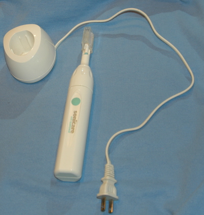
Wireless Power Transmission? You bet! You may have an electric toothbrush (see below) that seems to never need recharging. All you need to do is place it in the docking station and it runs forever??? However, the docking station still needs to be plugged into the wall. So what is this all about? This is nothing more than a transformer. The docking station has coils of wires embedded in the base with current moving through it. The base coils represent the primary windings of the transformer. The secondary wires are embedded in the base of the toothbrush itself. During docking, the changing magnetic fields in the base unit induce currents to flow in the secondary windings in the brush. These induced currents charge up a small battery. This technology has caught on in a device known as Splashpower® to recharge many types of devices using the same idea (including the newest iPhone).
At the electric company, the primary coil receives 110-120 volts AC
(mean) from the generators. A step up transformer converts this to a high
voltage ... which is sent to remote locations. At the substation, a
series of step down transformers eventually convert this back to 110-120 volts
(mean).
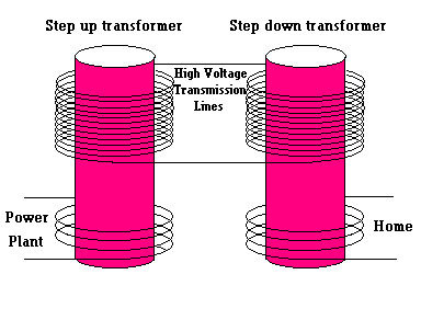
Thomas Edison (1847-1931) tried to bring electricity to homes in New York City in 1882. He used direct current (DC), but found that there were huge power losses as he tried to transmit electricity over long distances. This resulted from such a high current (lots of amps) in the transmission wires that the losses to electrical resistance were excessive. The solution came in the form of alternating current (AC) because step-up transformers were able to convert the lower voltage - high amperage power to high voltage - low amperage power. This allowed long distance transmission of electricity with much less power losses to heat. Those towering transmission lines coming out of power stations can be up to 500,000 volts (link 3.4.j). Once near the homes, step-down transformers could again be used to convert the high voltage - low amperage power back to usable form. This idea came from the Serbian-American inventor Nikola Tesla (1856-1943) and George Westinghouse (1846-1914). I just read a book called The Last Days of Night (link 3.4.k) which told the story of the battles Edison, Tesla, and Westinghouse had to establish a standard for the delivery of electricity to our homes. You already know the result - AC won that battle.
If interested, read link 3.4.l article to see how electricity is distributed from the power plant to your home.
The electric outlets in your home are connected to 2 wires (let's forget about the green "ground" wire for now). The black wire is "hot" ... meaning it carries 120 volts (on average) of AC with respect to the white or "neutral" wire. When you use an appliance (called the "load"), alternating current flows in both the black and white wires.
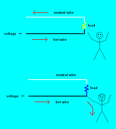
An electrical short circuit (animation)
If you accidentally touch the black "hot" wire, you could get a potentially lethal shock because you now become the "load" as your feet are in contact with the neutral earth. To prevent this scenario, most outlets in bathrooms or pools are protected by a ground fault circuit interrupter or GFCI for short. These devices are able to monitor the current in the black "hot" wire as well as the current flowing in the white "neutral" wire. Under normal conditions, these currents should be exactly the same. However, if you drop your hair dryer in some water, current flows directly to the earth (and bypasses the white wire). A sensor detects that there is an imbalance between the currents in the black and white wires, and something is wrong ... so it quickly energizes an electromagnet to stop the flow in all wires. But have you ever wondered how the sensor is able to sense this current imbalance?
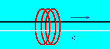
First you surround a small section of the black (hot) wire with a coil of wire. When AC current flows in this "hot" wire, it will automatically produce a changing magnetic field which induces currents to flow in this surrounding coil. The same can be said about the current flowing in the white "neutral" wire. The trick here is to direct the current in both wires so the flow is in opposite directions (much like cars moving in opposite directions on a 2 lane highway). Under normal working conditions, the magnetic fields from both wires will cancel each other out, and no currents are induced in this nearby coil. However, if current is flowing through your body, it flows in the "hot" wire, but not through the white neutral wire. This will instantaneously induce currents to flow in the nearby coil ... which energizes an electromagnet ... which opens all circuits.
An inductor is just an electromagnet (or a transformer without a secondary coil, but now the iron core is a necessary component). When an alternating current is sent through the coil, an interesting thing happens. Small "eddy currents" are set up in the iron core.
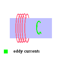
An inductor (animation)
These "eddy currents" induce currents back in the original coil! Electricians call this a "back emf" ... this is because the induced current is in the opposite direction as the one that originally produced it. This effect is found in all motors and transformers as well ... but we have ignored it to this point. However, some devices rely on the "back emf" to make them work.
For clarity, let's go through the steps here because it is a bit tricky:
Another thing to keep in the back of your mind is the fact that this whole process represents a conversion of energy forms. That is, electrical energy is converted to magnetic energy and then back to electrical energy. Remember the pendulum? When we study the way radios (and other wireless transmissions) work, we will come back to this example.
Metal detectors use the principles of induction to help you find your buried treasure (they are also used at traffic lights to detect if a car is at an intersection). This is because the buried coins (or your car) act as the iron core ... through which "eddy currents" can initiate a "back emf" to the coil that started it all. This return current is picked up and tells you that you have struck it rich!
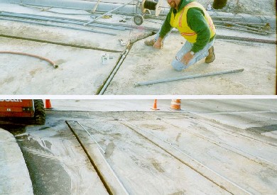
An induction loop being prepared in a future left turn lane
Induction loops are most likely found under most "drive-thru" windows ... giving the server a signal that a car is waiting.
A tool similar to a metal detector is used to detect small stress fractures in the frame of airplanes. If a crack was present, the eddy currents would encounter more resistance ... producing a weaker "back emf". The same idea may be used in quality control in the manufacture of metal items. Suppose you need to manufacture an aluminum sheet with a precise variance in thickness. You could pass the finished product under an electromagnet with AC current running through the coils. The eddy currents produced in the aluminum sheet should be consistent if the thickness of the material remains unchanged. However, if the thickness goes above your tolerance, you produce stronger eddy currents, and as a result, a stronger "back emf".
If interested, click link 3.4.m to see another Java applet.
©2001, 2004, 2007, 2009, 2016 by Jim Mihal - All rights reserved
No portion may be distributed without the expressed written permission of the author