Key Terms
dielectric
RC filter

A capacitor is a device that can "store" electric charges. It consists of two conducting plates separated by an insulated gap. Sometimes the gap is filled with glass, plastic, wax paper, air or oil. It is not a resistor because electricity (current ... or flow of electrons) really doesn't move through it (at least by design). It is not a battery (which puts out only one voltage) ... but can supply voltages of many different values.
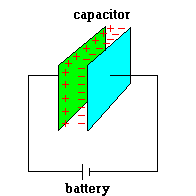
One way to charge up a capacitor is to connect it to a battery (see image above). Once charged, it will store electric energy. One way to release this energy (quickly) is to remove the wires from the battery and let the two wires touch. A spark is often produced. This should remind everyone that you should NOT think you are safe from getting zapped with dangerous currents when working on some device (air conditioners, computers, TV's, etc) ... even if it is unplugged.
Sometimes a battery goes dead on a device and yet your
settings still remain intact. Thank a capacitor. It powers the
device during the time you replace the batteries.
Capacitors are placed in the circuitry of off/on switches in
some cases. Ever see a spark (in the dark) when turning on some light
switch? This is because when a switch is flipped, a very tiny air gap
exists for a brief moment and the dielectric strength of the air is overcome.
To prevent this, a capacitor acts as a place to dump excess energy when this
small gap exists. For the same reason, capacitors (sometimes called condensers
for old timers) were used when cars required breaker points (in the distributor) to
ensure that the spark occurred at the proper time.
A capacitor can discharge all its stored energy in a tiny
fraction of a second, where a battery would take minutes to completely drain itself.
That's why the electronic flash on a camera uses a capacitor -- the battery
charges up the flash's capacitor over several seconds, and then the
capacitor dumps the full charge into the flash unit.
This idea is also used in stun guns and heart defibrillators.
Capacitors are used to "kick-start" huge electric motors
which always draw more amps on start-up.
These devices can be used to "smooth out" unwanted spikes
and valleys in voltage. You can think of these devices as a place to
dump excess energy, or to tap energy from if needed.
Because capacitors take a certain amount of time to charge
(and discharge), they make excellent analog timing devices in electronics.
By adding resistors in the circuit, you can make a capacitor discharge at
any rate you like. Some car lights stay on for a short time
after you leave. The timing is controlled by the discharge of a
capacitor.
The energy in a capacitor is actually stored in an electric field. When a capacitor is fully charged, each plate holds an equal but opposite electric charge. Since both places hold opposite charges, they tend to attract each other. There is energy in that ... electrical potential energy.
Let's draw an analogy between a charged capacitor and some weight elevated a certain distance from the ground. The capacitor is storing electric potential energy and the weight is storing gravitational potential energy. To release the energy stored in the capacitor, just let the wires attached to each plate touch and current will flow (you will get a spark). To release the energy stored in the weight, let it drop. The capacitor stores energy in an "electric field" just like the hanging weight stores energy in a gravitational field. Keep in mind that there is a certain voltage (potential difference) between the plates as long as there is some separation of charge between the plates.

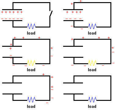
Discharging a capacitor (animation)
Note: The electrons are represented by the negative signs, and you can think of the positive signs as "holes"
Now consider the hanging weight. What are some ways we can increase the energy stored in the system? Obviously we can add more weights (at the same height) ... twice the weight means twice the stored energy. How can this be accomplished in the capacitor? By increasing the charge at each plate (put more +'s and -'s at each plate). This will increase the voltage and increase the energy stored in the system. If this "boosted" capacitor is shorted out, it will produce a bigger ZAP if you touch the contacts.
Another obvious way to increase the energy stored in the hanging weight system is to increase the height of the single weight. There is no difference when we consider the capacitor. If we move the plates farther apart, it will take a certain amount of work ... and if you believe the first law of thermodynamics, energy has to be added to the system. This will also increase the voltage between the plates. (In physics, one would say that we were decreasing the capacitance but increasing the voltage.)
There is another way we can change the energy in our "hanging weight" example ... but it is a little off beat. We can move the system to the moon! The strength of gravity on the moon is only about 1/6 that at the earth's surface. Since the gravitational field is weakened, the energy stored in that field is less. We can do the same thing with a capacitor by placing some insulating material between the plates. We call this a dielectric. By inserting a slab of glass, for example, the field is weakened and the voltage between the plates decreases.
Let's look at this effect a bit closer. What happens to the glass when it gets placed in this field is interesting.

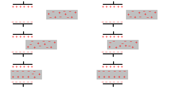
Watch what happens to the random charges in the glass (animation)
If you watch the animation, you will see that as the glass is inserted between the plates, random charges within the glass are "polarized". That is, rather than being randomly distributed throughout the glass, they are influenced by the external electric field and migrate in a preferred direction (remember, unlike charges attract). This takes energy! The energy required to create this charge separation comes from the energy stored in the electric field. This weakens the field and decreases the voltage between the plates.
These properties of capacitors make them excellent sensors. If you watch the animation closely, the charge separation is initiated well before the glass actually enters the capacitor. This is because the electric field is not confined strictly between the plates but "fringes" out the sides a bit. Have you ever seen electronic stud sensors at the local hardware store? (I grew up using a magnet ... looking for nail heads under the paint.) These stud finders have sensitive capacitors inside which are sensitive to small changes in voltage. The wooden wall stud becomes the dielectric when you move over it and a light goes on alerting you where to drive the nail.
Another example where capacitors can be helpful occurs when attempting to measure the humidity of the air. The dielectric properties of air vary with the amount of water vapor in the air. So all you have to do is charge up a capacitor and as the vapor content in the air varies, so does the voltage between the plates. This information can be fed into a microcontroller ... producing a digital display. This surely beats the older method ... where a strand of human hair was linked to a dial. As the humidity changed, the length of the hair would too ...producing a different dial reading. Here are more ways a capacitor can be used as a sensor:
Air bags are expensive to replace so auto manufacturers need
to find a way to avoid deploying air bags in the passenger seats if no one
is occupying that seat. One solution is to use capacitors as
occupancy detectors. That is, the human body becomes the
dielectric material between two plates. One plate of the capacitor is
embedded in the passenger seat (either in the form of a metal plate or
conducting fiber). The other plate of the capacitor may be the metal
frame of the car. Usually a reference capacitor is used (which is
shielded from the passenger seat) as a comparison. If a person
occupies the passenger seat, a change in capacitance is observed (and not in
the reference capacitor) which alerts the computer that someone is sitting
there. The same arrangement could be used to determine if a hand is in
danger of being trapped by a closing car window. The principle is not
just limited to human bodies. The change in capacitance could be used
to determine if a door is left open or safety gate is not in position
One type of touch screen is called a surface
capacitive touch screen. It works because the entire perimeter of the
screen is lined with charged metal strips which act like a complex system of
capacitors. When a person touches the screen, the finger acts as a
dielectric which alters the voltages in the system grid. Each place of the
screen you touch offers a unique pattern of voltage changes in the system.
This is sensed by a microcontroller and converted to an exact (x , y) location.
One way to measure the pressure of a gas (or liquid) is to
expose it to a flexible diaphragm. As gas pressure increases, it
forces the diaphragm to "bulge out". The greater the pressure, the
greater the deflection of the diaphragm. A capacitor is able to
accurately measure the amount of flex if one plate is attached to the
diaphragm itself and the second plate is held fixed with respect to the
system. As the pressure changes (flexing the diaphragm) the separation
of the plates changes and is picked up as a change in capacitance. A
microcontroller can convert this directly to a digital pressure reading.
This same principle can be applied to microphones since voice is
nothing more than pressure waves in the air. You should see that a
capacitor used in this sense can make an excellent position sensor.
Simply fix one plate to the target and you will immediately know if there is
motion with respect to the second (stationary) plate.
|
Capacitors in a microphone (animation) |
Remember:
If the distance between the plates of a charged capacitor
varies ... so does the voltage across the plates ... which can be picked up
by a microcontroller
If something goes between the plates of a capacitor (or even goes near the plates) ... the dielectric properties change ... so does the voltage across the plates ... which can be picked up by a microcontroller
The electronics industry makes extensive use of capacitors by virtue of their ability to act as filters. For example, consider the animation below:

Capacitors block DC current but not AC current (animation)
Two identical circuits are shown with differing power sources. The left side uses DC and the right is shown with AC power. When the switch is closed, the DC circuit lights up briefly and then ... nothing! The light goes on briefly as the capacitor charges up, but since no electrons actually pass between the plates, there is no conducting path to follow. The situation is completely different in the circuit powered by alternating currents. On the positive side of the AC signal, electrons are fed in one direction and the capacitor charges up (and the light goes on). Soon the power source flips to negative and the current in the circuit changes direction. The capacitor discharges and recharges with the opposite polarity. Again the light stays on. The cycle continues and the light never goes off (even though no electrons actually pass through the capacitor).
That last statement is a bit of a lie. Actually the light in the AC circuit may go off briefly because once the capacitor is fully charged, it may have to wait around a while until the AC signal changes polarity. You may not ever see the flicker, but it may dim the bulb a bit because you are limiting the amount of current through the filament. From this discussion you can possibly see that the frequency of the AC signal has an effect on the way it interacts with the capacitor (as well as the light bulb). To get the maximum current though this system it needs to be timed in such a way that the charge/discharge cycle of the capacitor matches well with the frequency of the AC source. By adding resistors to the circuit, the charge/discharge time of the capacitor can be altered. In this way resistor - capacitance (RC) systems can become efficient ways to pass signals of one frequency and block out (or reduce) unwanted waves of different frequencies.
We have limited this discussion to power delivered by the utility which is locked at a frequency of 60 Hz. In reality, signals with a wide range of frequencies can be considered if we look at music. The electronic signal we get from a simple song is the sum of a multitude of signals all added together. Suppose you only want to filter out waves which produce higher pitches and send them to a tweeter. An RC filter placed in series will do the job quite well. The woofers are designed to accept waves from the lower pitch sounds, so just make sure the signal to that speaker has a different RC filter in place.
Ham radio operators frequently use RC filters to block out 60 Hz
line "noise" to get a better signal
Car audio systems use RC filters to eliminate unwanted engine noise from an audio setup in much the same way.
Note: A thorough discussion of RC filters is well beyond the scope of this course. The behavior of signals and how they are modified by resistors, capacitors, and inductors is challenging, to say the least. I hope this approximation at least gives you an appreciation of the ways these items can be useful.
©2001, 2004, 2007, 2009, 2016 by Jim Mihal - All rights reserved
No portion may be distributed without the expressed written permission of the author