
Digital image of a handsome guy

A close-up of the eye
Key Terms
algorithm
ASCII code
binary system
bit
Boolean Logic
byte
full adder
gates
truth tables
Incredibly, a computer only works with two things - "0"'s and "1"'s. When information is reduced to this level of simplicity, it is called digital. You have already learned how a computer stores these "0"'s and "1"'s on a hard drive, CD, and in RAM, but how does it make any sense out of just two symbols? It all depends on how these two digits are organized.
If you have ever had a chance to study the Braille system, you would see that it, too, is digital - dot or no dot. Yet you can read or write an entire book in Braille. Click link 7.6.a to convert text to Braille. The Morse code uses just 3 "bits" to encode information - dots, dashes, and spaces. Click link 7.6.b to convert your message to Morse code. DNA uses just 4 chemical bases to encode your entire genetic code. Note: So far, nature is way ahead of us at efficient methods of encoding information at the molecular level. As you work through this section, you will see the many ways a computer uses just two digits (0 and 1) to organize or encode information.
Computers use a code to translate digital information into letters (and other
keyboard characters). This code is known as the ASCII code
(American Standard Code for Information Interchange).
Link 7.6.c lets you see the translations. You can see from the chart
that the letter "A" is represented by the decimal value 65 (which is 1000001
binary ... actually 01000001). Each keyboard character can be expressed
as a single byte ( 8 bits) of data. The ASCII table allows 28 or
256 possible distinct characters.
Images can be digitized. Consider this image:
|
Digital image of a handsome guy |
A close-up of the eye |
If you zoom into a small section (the eye, for example) ...you would realize that the image is simply a collection of pixels of different colors. Each color has a digital value assigned to it, and there are many different ways of encoding that information to construct the final image.
Probably the easiest to understand is a bitmap image. Each individual pixel is assigned a color number. An 8 bit image means each pixel is saved as an 8 bit number, so there are only 28 or 256 possible colors to choose from (your palette size). A 24 bit image means each pixel is saved as a 24 bit number. This allows 224 or over 16 million colors to choose from (a much bigger selection of colors), but this also means the image will take up more disk space. Other techniques for storing images help reduce the size of the file. A format called GIF (Graphics Interchange Format) is widely used on the Internet where the image is limited to 256 colors (great for drawings ... plus it supports animations ... many of which you have seen), but rather than storing each pixel as a number, it stores a pixel value and indicates how many times that same color is used in the adjacent pixels. For example, draw green for the next 25 pixels. Another format called JPEG (Joint Photographic Experts Group ... a.k.a. jpg) is also an Internet standard because it uses a compression algorithm which greatly reduces file size. JPEG is great for compression of photographs, but you will lose quality because the compressed image is NOT the same as the original. This lets you trade file size for image quality. The good news is, JPEG offers a 224 color palette and most programs let you decide how much compression is used. Basically the developers of this format realized that the human eye does not notice slight changes in color (in adjacent pixels) so it looks for ways of altering groups of pixels in the original image so the same area gets "smeared" into a cluster of nearby colors. Finally, a newer Internet format called Portable Network Graphics (PNG) will eventually replace the GIF format due to a better file compression scheme.
If you routinely take pictures (with a digital camera or smart phone), you probably know that the file size for one image can be huge (depending on your default setting). A single image might take 5-30 megabytes. This is far too large for sharing between phones or posting on the Internet. This is why it is necessary to compress the image using one of the formats mentioned above. There are a lot of DO's and DONT's (which I did below). Another factor to consider is whether the format is lossless or lossy. That is, does the format retain ALL the original information (lossless) or is the compression a close approximation to the original data (lossy). Link 7.6.d does a nice job explaining this. Compression is not only used for images, it is done for videos, music, and files. Computer geeks (now a badge of honor) know that you can compress any file (or group of files) into one lossless ZIP file. Did you know this algorithm was invented by a Milwaukeean, Phil Katz?
 JPG image (29 kb) |

... converted to a PNG image (193 kb). I converted |
 ... then to a GIF image (39 kb) ... a very poor choice for photographs since the pallet is limited to 256 colors.. |
If interested, click link 7.6.e for more information.
Click link 7.6.f to hear a short greeting in uncompressed WAV format or click link 7.6.g to hear it in compressed MP3 format.
Each tone of a sound wave is actually an analog signal which is converted to a binary number. This is done by "sampling". That is, the wave is chopped up into many slices, and each slice is assigned a numeric value to the amplitude.
![]() This is an analog signal (varying voltage).
This is an analog signal (varying voltage).
For example, an 8 bit, 22 KHz sound clip means the analog signal is sampled 22 thousand times per second and each separate tone is recorded as an 8 bit number. This provides 256 distinct tones. CD quality sounds are sampled at 44 KHz at 16 bit quality (giving 216 or over 65 thousand possible tones).
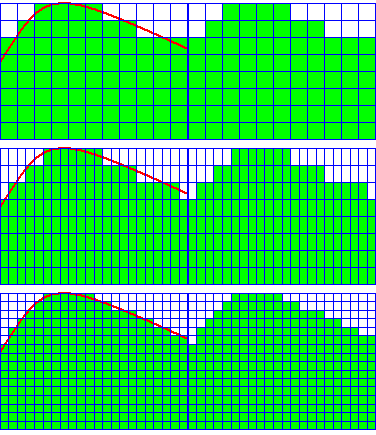
This animation shows how sampling works
The animation above can serve as a visual example. Suppose the red curve represents the wave form of a short section of a sound clip. Originally, the clip is divided into 11 distinct samples, and each sample is limited to 8 distinct values. This will take a relatively small amount of data to encode, but the data makes a rather poor estimate of the original wave form. The quality can improve if you increase the number of samples to 22, but the amount of data required to estimate the curve also doubles. Finally, if each sample is then increased to 16 distinct values, the estimate improves dramatically, but so does the amount of data needed to store that information.
A numbering system that uses only two digits (0 or 1) is called a binary system or base
2. Incredibly, any number you can write in the traditional (base 10)
system can be expressed as a string of bits (0's or 1's).
Traditionally, bits are
strung together in groups of 8 to form bytes. For simplicity in our
discussion, we will not express numbers beyond the one byte limit.
8 bits (1 byte) strung together looks like this: 01101001. How many different numbers can be expressed with one byte? The number of different possibilities is 28 or 256. For computers, you start counting at zero, so any number from 0 to 255 can be expressed as 1 byte. I will take you through a number of steps that will need to master in order for you to see how a computer does the same task.
Example #1 - Let's convert the binary number 11001101 to its decimal (base 10) equivalent.
In the normal counting system (base 10), columns are based on powers of 10 ...ones, tens, hundreds, thousands, etc. However, in binary, the columns are based on powers of 2 ... ones, twos, fours, eights, etc. It is easy to convert from binary to decimal as long as you know what value each column holds.
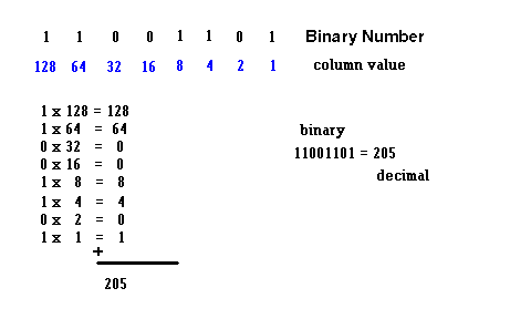
You should be able to convert any (8 bit) binary number to its decimal equivalent. Use link 7.6.h to check your results.
Question #1: Convert 10101010 to base 10 (see answer below).
Question #2: Convert 11001100 to base 10 (see answer below).
If you can divide by two, you can convert any number to base 2.
I'll choose a number and show the procedure. Make sure you can do the same for any number between 0 and 255.
Example #2 - Convert 137 (base 10) to base 2.
Answer: We will restrict ourselves to 8 bit answers so the format we expect will be xxxxxxxx
137 divided by 2 = 68 remainder 1. The remainder fills the rightmost column. xxxxxxx1
68 divided by 2 = 34 remainder 0. The remainder takes the adjacent column. xxxxxx01 ... now just follow the same procedure ....
34 divided by 2 = 17 remainder 0 -----> xxxxx001
17 divided by 2 = 8 remainder 1 -----> xxxx1001
8 divided by 2 = 4 remainder 0 ----> xxx01001
4 divided by 2 = 2 remainder 0 ----> xx001001
2 divided by 2 = 1 remainder 0 ----> x0001001
1 divided by 2 = 0 remainder 1 ----> 10001001
137 (base 10) = 10001001 (base 2)
Please be able to convert any number from 1 -255 (base 10) to binary (base 2). Click link 7.6.i or link 7.6.j to check your answer.
Question #3: Convert 213 (base 10) to binary (see
answer below).
Question #4: Convert 65 (base 10) to binary (see answer
below).
We just showed how to convert between bases. How can you get a computer to do the same thing? The trick is to have an algorithm. That is, a step by step procedure or a set of rules that a computer can follow to solve a problem. Telling the computer these rules and asking it to carry them out requires a program. A program is nothing more than software ...code that a computer understands. The problem is, humans organize data in a very different way than the way computers do. Early programmers initially tried to write these rules in "machine language" and often made so many errors that their programs never ran. The solution came with the development of higher level languages. That is, ways of producing computer codes which were easier for humans to work with. Some early computer languages were Fortran and Cobol. Beginners can learn the essence of programming with languages like BASIC or Visual BASIC. There are currently thousands of programming languages such as Java, C++, HTML, etc. The codes that programmers write are translated to a language the computer understands. Although we will not go into great depth, we will attempt to show (below) how a computer is capable of doing some simple math using logic gates made from switches.
A computer solves problems by a system known as Boolean Logic. It is based on the logic of truth tables. Each one of these logic tables can be represented by a system of switches (transistors or electromagnetic relays) on a circuit board and is known as a gate. Think of a gate as a type of machine where you put something in and you get something out. In this case you only put numbers in and only get numbers out. Easier yet, the only numbers used are zero and one.
Below are three very basic truth tables:
A NOT Table
| Input Value | Output Value |
| 1 (true) | 0 (false) |
| 0 (false) | 1 (true) |
This is described verbally as "the opposite of". That is, it returns just the opposite of whatever is put in.

Since an electromagnetic relay is easier to visualize than a transistor, the relay below represents a NOT gate.
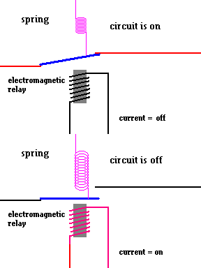
Implementing a NOT gate using a relay. OFF = 0 ON = 1 Think of the input as the current in the electromagnet and the output as the current in the relay. (animation)
The AND Table
| Input A | Input B | Output Value |
| 0 | 0 | 0 |
| 1 | 0 | 0 |
| 0 | 1 | 0 |
| 1 | 1 | 1 |
Now we have two input values. This is described verbally as "only if A and B". That is, it only produces a 1 for output when A AND B are both 1. For example, you can only pass this class if you register for the class AND earn passing grades.

Notice that the relays below only complete the circuit when both switches are on.
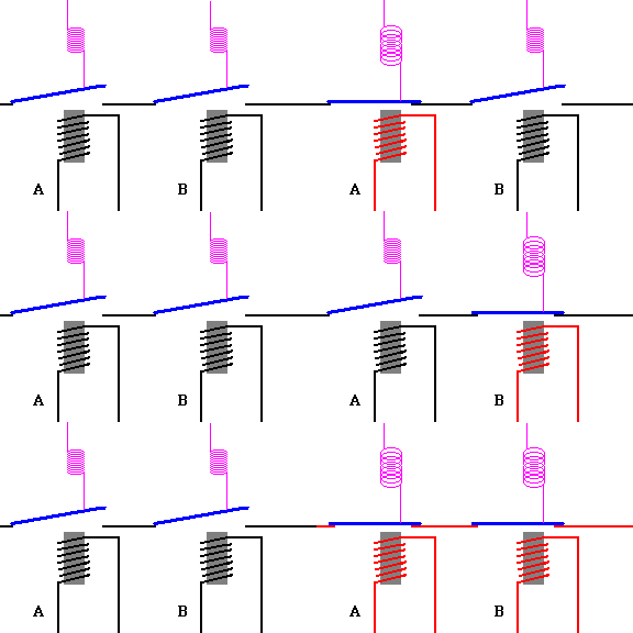
Implementing an AND gate using relays. (animation)
The OR Table
| Input A | Input B | Output Value |
| 0 | 0 | 0 |
| 1 | 0 | 1 |
| 0 | 1 | 1 |
| 1 | 1 | 1 |
This is described verbally as "only if A or B or both". That is, it will produce an output of 1 if either A = 1 OR B = 1 For example, you can purchase an item with cash OR with a credit card (or both).

Again using relays this can be shown as follows:
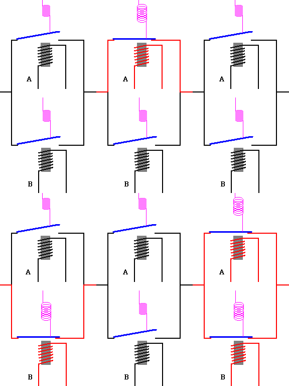
Implementing an OR gate using relays. (animation)
From these three simple logic gates, more complex logic gates can be constructed ... namely an XOR gate and an XNOR gate. Here are the truth tables for each one of these gates:
The XOR table (exclusive OR)
| Input A | Input B | Output Value |
| 0 | 0 | 0 |
| 1 | 0 | 1 |
| 0 | 1 | 1 |
| 1 | 1 | 0 |
This is known as the Exclusive - OR gate and is described verbally as "only if A or B, but not both".

The XNOR table
| Input A | Input B | Output Value |
| 0 | 0 | 1 |
| 1 | 0 | 0 |
| 0 | 1 | 0 |
| 1 | 1 | 1 |
This is known as the Exclusive - NOR gate and is described verbally as "only if A is the same as B".

Each of these gates can be constructed using combinations of the NOT, AND, and OR gates already discussed. That is, we can use these simpler gates to construct more complex gates. For example, here is one way you can construct an XOR gate:
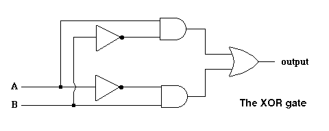
It is worth your effort to trace different values of A and B through the diagram to actually see that this gate produces the desired truth table. The animation below traces values through the XOR gate when A=1 and B=0. The table above says the output value should be 1.
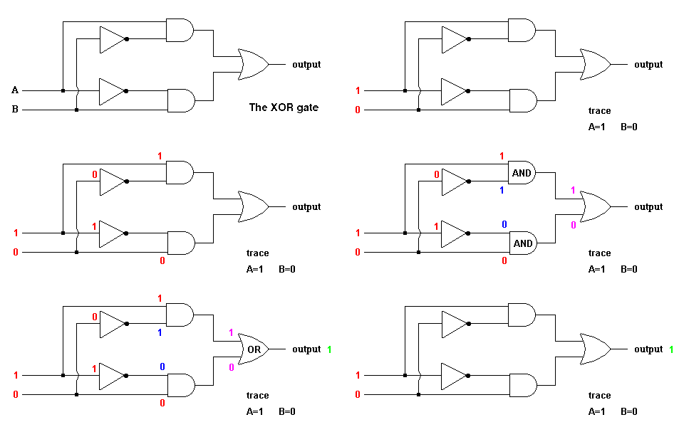
Tracing values through gates (animation)
Why have we put you through this maze? Because with these logical gates, a computer can manipulate numbers ...starting with addition. If we can show you how a computer can add two binary numbers, it is a simple step to see how it can subtract numbers (by adding the opposites). From there you get multiplication ... which is just many additions (3 x 5 = 5 + 5 + 5) ... and it goes from there.
Please add these two base 10 numbers on paper: Add 574 to 253. You learned an algorithm in grade school to do this (I hope you still remember it and got an answer of 827.)
Ok, let's do this again but this time we need to be super technical. You started in the rightmost column (sometimes known as the one's column). You added 4 + 3. Your output was 7 so you wrote that down first. There was nothing to "carry over" to the next column so you ignored it (but technically, the carry over was 0 - zero). Now you went to the middle column (known as the ten's column) and you added 5 + 7 ... but really, you added 5 + 7 + 0 since there was nothing "carried in" from the last computation. You got an answer of 12 but you didn't write that down .. did you? Your output was actually 2 with a "carry over" of 1. Finally you went to the leftmost column (the hundred's column) and added 2 + 5 .... but really you added three numbers since there was a "carry in" from your last calculation. That "carry in" was 1. You added 2 + 5 + 1 to arrive at an output of 8 with nothing to carry over to the thousand's column. You were done. Congratulations, you successfully completed the base 10 addition algorithm. Now let's cover the base 2 addition algorithm.
We start with some basic rules, namely:
0 + 0 = 0
0 + 1 = 1
1 + 0 = 1
1 + 1 = 10 (Not "2"
because this symbol is not allowed. The binary equivalent of 2 is written 10.)
Actually, we need to say ....
0 + 0 + 0 = 0
1 + 1 + 0 = 10
1 + 0 + 1 = 10
0 + 1 + 1 = 10
1 + 1 + 1 = 11 (again ...
base 2)
With that, let's add some numbers by hand. Consider this problem ...
Just like you would in base 10, you start at the rightmost column and follow the "rules" listed above. The output is displayed in blue. Sometimes you need to "carry over" numbers to the next column (displayed in magenta). Sometimes you need to "carry in" numbers from a previous addition (displayed in green).
|
Adding the "1's" column |
Adding the "2's" column |
Adding the "4's" column |
Adding the "8's" column |
|
Adding the "16's" column |
Adding the "32's" column |
Adding the "64's" column |
Adding the "128's" column |
Final results
Question #5: add 01100110 + 00111101 by hand (see answer below)
Question #6: add 01010101 + 001001 by hand (see answer below)
You should be able to add any two binary numbers by hand. A computer needs to be able to do the same thing!
First, the computer needs "rules". I've listed them below and you should see they are basically the rules we listed above (only a bit more ordered .... bad pun):
Basic rules
0 + 0 + 0 = 00
0 + 0 + 1 = 01
0 + 1 + 0 = 01
1 + 0 + 0 = 01
1 + 1 + 0 = 10
1 + 0 + 1 = 10
0 + 1 + 1 = 10
1 + 1 + 1 = 11
The computer only adds two digits at a time (one column at a time), however, the reason we need to include a 3rd digit is because an addition may involve a "carry in" digit from a previous calculation. In fact, the algorithm will always allow for a "carry in" and simply assign it a value of 0 or 1. Also, you will notice that all the answers are in a 2 digit format (00, 01, 10, or 11). The right most digit is considered the "output", and the leftmost digit is the "carryover" (a digit that is considered later, when adding the next column).
|
How a computer breaks down the addition of A and B |
|
To help see this, try adding 11 + 01 manually. I'll assume you can add the first column together with no problem and we can start the analysis when you attempt to add the second column of numbers. At the second column, you are adding 1 + 0 with a "carry in" value of 1 (which was the "carry over" value when you added the first column).
The graphic below shows a colored coded display of all the values.
All we need to do is construct a logic table that produces the appropriate results. A careful analysis shows that the table below follows all the "rules" we assigned for binary addition.
Basic rules for addition
0 + 0 +
0 = 00
0 + 0 +
1 = 01
0 + 1 +
0 = 01
1 + 0 +
0 = 01
1 + 1 +
0 = 10
1 + 0 +
1 = 10
0 + 1 +
1 = 10
1 +
1 + 1 =
11
Logic table needed
|
A |
B |
CI (carry in) |
CO (carry over) |
Output |
|
0 |
0 |
0 |
0 |
0 |
|
0 |
0 |
1 |
0 |
1 |
|
0 |
1 |
0 |
0 |
1 |
|
1 |
0 |
0 |
0 |
1 |
|
1 |
1 |
0 |
1 |
0 |
|
1 |
0 |
1 |
1 |
0 |
|
0 |
1 |
1 |
1 |
0 |
|
1 |
1 |
1 |
1 |
1 |
Now all we need to do is find a way to implement this table's logic....
A computer with this type of logic circuitry will be able to add any two binary numbers, ... and here is how it was originally all put together using gates:
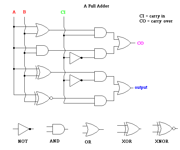
Clever digital designers are always looking for ways to do the same thing with less circuitry. The "original" full adder can be replaced by the following arrangement of logic circuits.
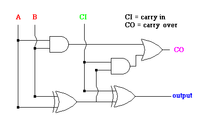
The improved full adder
In the following animation, we will trace the following values, through this logic gate:
|
A |
B |
CI (carry in) |
CO (carry over) |
Output |
|
0 |
1 |
1 |
1 |
0 |
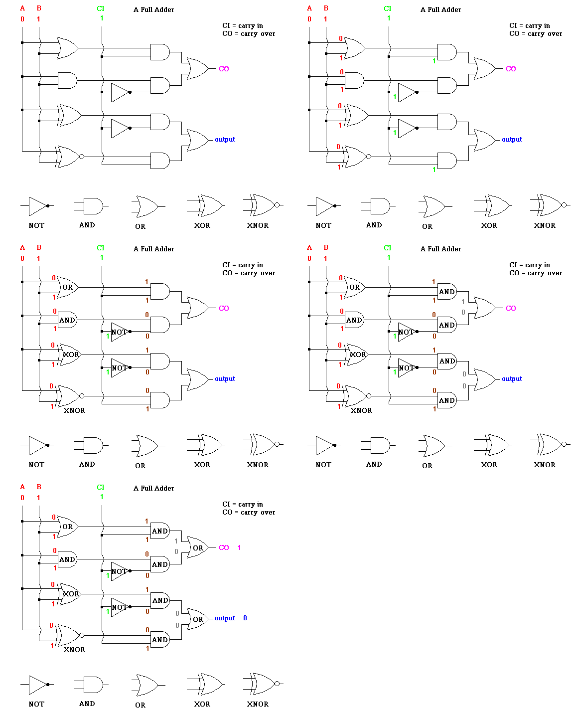
Tracing values through a "full adder" (animation)
I also have a slideshow of this animation which lets you stop the action and view the details one slide at a time. Click link 7.6,k
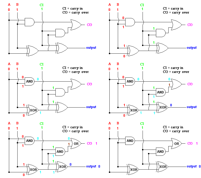
Tracing values through another "full adder" (animation)
To trace any values of A, B and CI through either full adder to produce the correct output:
Although this might seem like a lot of work just to add two digits together, a computer can run values through these gates at light speed. When it is finished with one column, it moves to the next column and repeats the process. Can you imagine how noisy the first computers were when all the switching was done by mechanical relays? As stated before, subtraction is done by adding opposites (12 - 5 = 12 + -5), multiplications by adding many times (3*8 = 8 + 8 +8), and divisions are accomplished by successive subtractions (24 ÷ 8 = 24 - 8 - 8 -8). And that is just simple arithmetic! Imagine how complex operations such as square roots and logarithms must be.
The algorithm for binary addition can be stamped on a computer chip using combinations of many logical gates. Once you appreciate this fact, you may realize that any algorithm (procedure) can be encoded on a microcontroller. Those of you who write computer programs already realize that any software is the result of intricate computer code or instructions which make the software "come alive". So too, digital designers make programs "come alive" on silicon chips by applying sophisticated circuitry. Given the appropriate arrangement of circuitry (logic gates, for example), along with clever software programmers, a computer can play chess better than the world champion, drive a car drive by itself, even become your doctor. The limits are set by OUR imagination.
Link 7.6.l does a great job showing how a digital designer is able to solve a problem using logic gates. Enter a prime number and a light goes on.
©2001, 2004, 2007, 2009, 2016 by Jim Mihal - All rights reserved
No portion may be distributed without the expressed written permission of the author
Answer #1: 10101010 = 170 (base 10)
Answer #2: 11001100 = 204 (base 10)
Answer #3: 213 = 11010101 (base 2)
Answer #4: 65 = 01000001 (base 2)
Answer #5: 10100011
Answer #6: 01011110